|
Title: |
1880 Article-Brown & Sharpe Mfg. Co., Tool Grinding Machine |
|
Source: |
American Machinist, 31 Jan 1880, pg. 3 |
|
Insert Date: |
7/7/2015 12:12:15 PM |
Tool-Grinding Machine
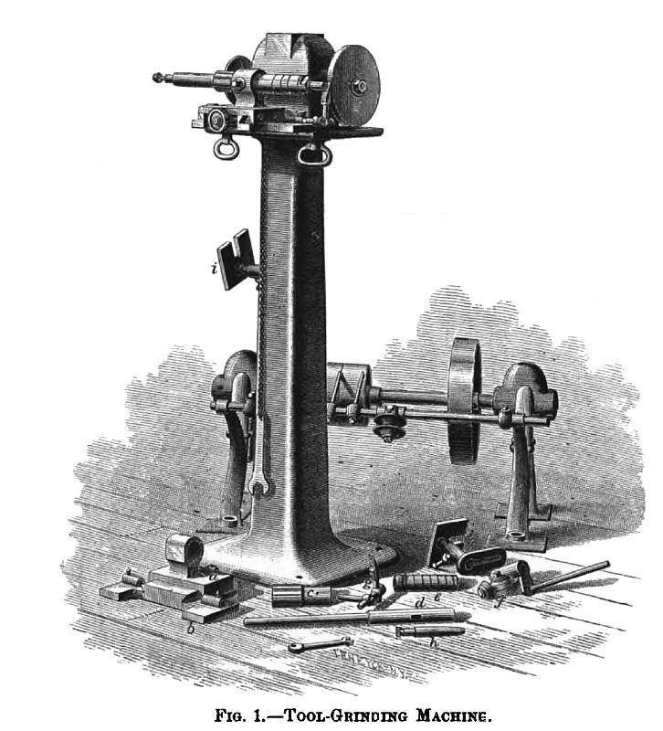
The use of emery wheels in machine shops, for grinding small tools, seems at the present day to have become as indispensable as the grindstone in our "grandfather's days." For common purposes an emery wheel attached to a spindle which is driven by a belt, seems to have met all requirements; this is, no doubt, for the rougher classes of work all that is necessary. But for grinding milling cutters and other tools which require the greatest exactness, something more is required. To meet this demand, the machine illustrated by Fig. 1 has been designed, and is now being manufactured with recent improvements by the Brown & Sharpe Mfg. Co., of Providence, R. I.
It consists of a plain base and a square upright column (see Fig. 1), on the top of which is placed an arbor carrying two emery wheels. One of these wheels may be of fine and the other coarse emery, in order that the coarse wheel may be used for grinding tools, thereby greatly increasing the utility of the machine.
The arbor is made of steel which runs in boxes ground to a perfect fit; these bearings are self-lubricating, and are securely enclosed so as to exclude all emery and dust arising from the grinding operation. The jacket or covering also excludes all dirt from the belt and pulley. The adjustable slide-rest a, attached to the plate b, forms a support for the arbor d. This arbor has a tapered hole in the end for the purpose of inserting changeable centers or small mandrels A, which are necessary for holding small shell-reamers and mills, and other small or complicated tools for grinding. The arbor is securely held by a close - fitting sleeve e. This sleeve is provided with small longitudinal grooves in order that it may be turned by the operator. A set-screw placed in the slide-rest a, will hold the spindle firmly in any position as may be desired. A shell e, is fitted so as to slide upon the smaller parallel portion of the mandrel d, and is used for holding milling cutters. This sleeve is provided with collars to accommodate cutters of all widths.
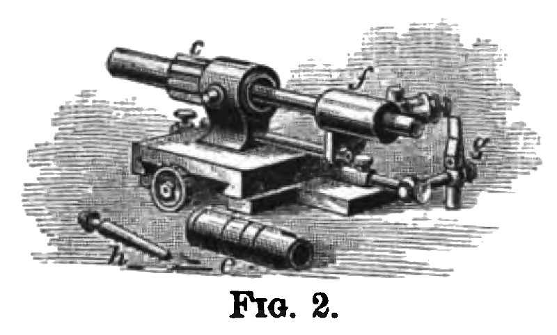
In grinding milling-cutters it requires great accuracy in order to have all the cutting edges alike and having the same clearance. The cutter being placed upon the sleeve e, is then set in front of the large emery wheel so that it may be moved across the face. A tooth-rest g, is then placed in position as shown, and not only guides the cutter, but also serves as a gauge for the proper clearance. The reader will understand from this description that a cutter may be ground quite rapidly by moving it across the face of the wheel, and rotating it so as to cause every tooth to pass over the gauge successively. A holder f, graduated on the edge, can be applied as shown in Fig. 2, for the purpose of grinding spiral or bevel cutters. By means of the graduations the holder may be adjusted to suit all angles. The projection from the bottom of the holder /, has a slot in it, so that by loosening a nut on the end of the guide-rod it may be set to give the cutter the proper clearance. When it is desired to use the machine for grinding common tools the slide-rest may be removed and the plain tool rests ii put in place of it, and when not in use may be hung upon the column. This machine is furnished with a counter-shaft with self-adjusting hangers and self-oiling boxes. Cutters may be ground on this machine as large as 4” long and 5” diameter. |
|
 1880 Brown & Sharpe Mfg. Co., Tool Grinding Machine
 1880 Brown & Sharpe Mfg. Co., Tool Grinding Machine Attachments
|
|