|
Title: |
1880 Article-E. E. Garvin & Co., Cutter Grinding Machine and Screw Slotting & Milling Machine |
|
Source: |
American Machinist, 01 May 1880, pg. 1 |
|
Insert Date: |
7/7/2015 9:19:22 PM |
Some New Shop Tools
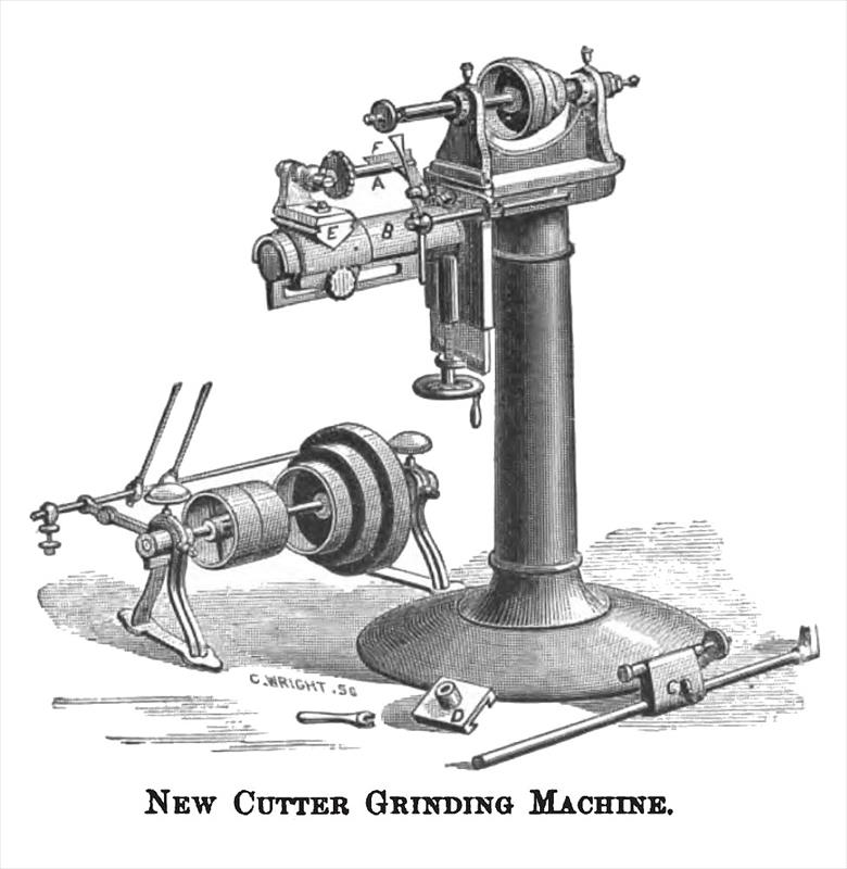
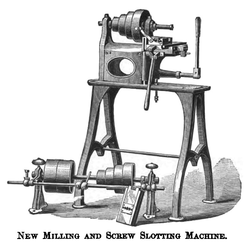
On this page are shown engravings of two new machines manufactured by E. E. Garvin & Co., 139 Centre St., New York. The first of these, a cutter grinding machine, is designed for sharpening all styles of mills, reamers and face mills, straight, spiral or beveled. The revolving spindle takes the arbor for holding the emery wheel. The front slide has an arm standing out under and in a parallel line with the revolving spindle. On this arm is a sliding platform which takes an adjustable slide that holds a straight arbor, and on this is a bushing which slides freely, and the mill to be sharpened is put on this bushing and moved along under the emery wheel. By previously adjusting the adjustable finger, to the tooth of the cutter to be ground, and by keeping the tooth against the finger, a perfectly true edge is secured. All necessary adjustments are provided for straight, taper, and spiral cut mills, with free backing on the cutting edge. For sharpening face mills, or those that cut on the end, there is an extra platform D, which is put in place of piece E. For solid reamers and shank cutters—arbor A is removed and C put in center. The front side is moved up and down by the hand wheel below, to adjust for diameter of mills and emery wheels. B, is an apron or shield to protect the slide and arm from emery and steel cuttings. F, is a rest which is to be used when common grinding or polishing is wanted to be done by using a larger wheel. The cone has three grades of speed. This machine is calculated to do a large range and variety of work of its kind, and will take mills from ½ to 7½ inches in diameter, and face mills to 12 inches diameter. Its weight is about three hundred pounds. The second machine shown is well arranged for taking short milling cuts, and can be operated with great rapidity. The box shaped head is mounted on a planed iron table surrounded by a trough gutter to catch oil and chips. The cross slide is adjusted by a screw that projects in front, squared for a wrench. The sliding table is operated by a hand-lever, and the motion is gauged by an adjustable stop behind. A vertical adjustment is communicated to the knee slide by means of a rack and gear, operated by a hand lever in front as shown in the cut; or, in case this convenient up feed is not required, a screw, that is operated by a hand wheel from beneath the table, is substituted in the place of the rack and gear. The spindle, which is of steel, has a 17/32 inch hole clear through it, tapered in front to receive the shank of the arbor. The boxes are made of box metal composition, and, it is claimed, are fitted up in a very substantial manner.
For slotting screws, a sliding vise is made, and is so arranged that the front or movable jaw tightens on the screw to be slotted, by means of two springs under the jaw. The jaw is linked so that it is operated wholly by the hand lever.
The screws are fed through under the saw.
With the machine having the lever vertical motion, as shown in cut, screws can also be fed up under the saw, which greatly increases its capacity. |
|
 1880 E. E. Garvin & Co., Cutter Grinding Machine
 1880 E. E. Garvin & Co., Screw Slotting & Milling Machine
|
|