|
Title: |
1856 Article-John McDowall & Sons.,Traverse Cross-Cut Circular Sawing Machine |
|
Source: |
The Practical Mechanics Journal, V8 Jun 1856 pgs. 223-225 |
|
Insert Date: |
8/20/2015 12:54:15 PM |
TRAVERSING CROSS-CUT CIRCULAR SAWING MACHINE
The wondrous mechanical stores of the "laboratory" in the Royal Arsenal at Woolwich, which we are so fond of showing off to inquiring foreigners as amongst the leading industrial achievements of our country, have lately received some important additions in the timber-converting machinery, invented by Mr. John McDowall of Johnstone, and erected by his firm. Two distinct forms of timber-sawing machinery, put up by this Scottish firm, are now in successful work in the arsenal. One of them is a cross-cut circular sawing machine, contrived so that the saw comes upon its out against the timber, and not the timber to the saw; in the other example, the saw is stationary and of reciprocatory action, being a modification of the ingenious system of stretching saws, illustrated by us in our Plate 123, by the “high-speed tensional sawing machine” of the same makers. Both arrangements present features of great novelty, and both are therefore fittingly selected for the examination of the readers of the Practical Mechanic’s Journal.
In the instance of the traversing circular saw, the saw disc itself is a great curiosity, being nearly seven feet in diameter, the largest yet made from one solid piece of cast-steel. Its driving gear is also a novelty, the saw spindle being totally unconnected with the actuating power, which communicates its motion to the saw disc through a couple of frictional cones, embracing the saw disc, one on each side, and rotating in concert at a high rate.
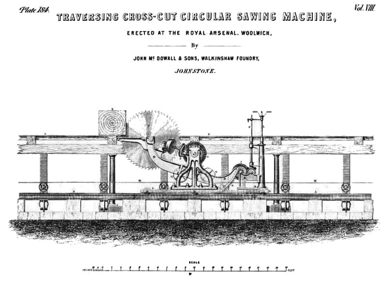
Our Plate 184 exhibits a full side elevation of this sawing machine in complete working order. Its foundation consists of n. cast-iron bedplate, A, 70 feet in length, that is to say, of the entire width of the sawmill house. This base plate is disposed horizontally upon stone bearers on a massive masonry foundation, in a sunk area under the mill floor, and in front of the vertical saw frames; and it is similar to the bed of an iron planing machine, occupying a breadth of about six feet. This bed-plate has upon it a heavy travelling carriage, n, mounted upon rollers capable of traversing along the bed-plate as upon a railway. The carriage sustains a pair of parallel vertical bracket standard pedestals, C, the two bearings in which form centres for the spindle acting as the supporting centre of the long differentially-curved beam, D, which has liberty to vibrate between the standards; this beam is composed of a central inverted T piece, answering as the suspending portion, and two long beam pieces bolted to it fore and aft. The after portion, or that to the right, is fitted with a toothed segment, E, whilst the opposite length is forked, or formed with a long deep double eye, to receive the bearings of the spindle of the circular saw, F. This vibrating beam support for the saw affords the means of setting the saw disc above or below the floor line, G, of the mill at pleasure; this being effected by turning the vertical spindle, H, accordingly. This spindle, which is supported in collar hearings in bracket pieces cast upon the pillar, I, of the carriage, carries at its lower end a bevel pinion in gear with a corresponding pinion fast upon a short horizontal shaft, which again carries a spur pinion in gear with the spur wheel, J; the shaft of this wheel carries a small spur pinion in gear with the toothed segment of the large vibrating beam. The two spindles of this short train of gearing are carried in hearings in the brackets, K, on the traversing carriage, so that the entire arrangement works together. The other spindle, L, having a double hand-lever on its upper end, serves for effecting the traverse of the saw carriage along its bearing rails; this spindle, L, passes down the centre of the pillar, I, and its lower end carries a spur pinion in gear with a spur wheel on a vertical stud spindle in the base of the carriage frame. The stud spindle of this wheel carries a spur pinion in gear with a horizontal toothed rack, extending along the whole length of the bed-plate. Thus, by turning the handle of the spindle, L, a powerful traversing force is obtained for setting the saw at any horizontal position in the house. The band-lever being capable of transshipping from one spindle to the other, the horizontal and vertical shifts of the saw can be performed with great facility and convenience.
Immediately over the saw, and on a level with the working floor, O, of the mill, there are two lines of cast-iron plates laid across the entire width of the house, and between these plates there is a space, 1¾ inches wide, to allow of the saw’s elevation for operating upon the timber at any part of the mill. The two shafts, H and L, for elevating and depressing the saw, and for traversing the carriage, pass through this opening, and as they may be misshipped at pleasure, the floor may at any time be cleared from all obstructions. The rotating cutting action of the saw is communicated through the spindle which works in the bearings of the standards, C, and forms the centre for the vibrating beam, D, this spindle carrying a belt pulley for the endless driving belt, M; on the same spindle are two opposed mortised wooden-toothed bevel wheels, O, each working into a cast-iron bevel pinion, P, set one on each side of the saw blade on an inclined shaft, the after end of which runs in a bearing carried by the central portion of the main vibrating beam; whilst the front end of the spindle is set in a bearing adjustable by a screw and dovetail face piece on the front curved end of the beam, D. This nicety of adjustment is necessary for setting the buff-leather cone pulley, carried by the inclined shaft on each side of the saw, hard up to the disc face, to nip it firmly near its periphery. With this ingenious arrangement, the whole of the saw disc is available for cutting, from the circumferential teeth quite up to the central binding washers, there being no pulleys in the way of the timber, as there are when saws for cross-cutting are driven in the usual way.
The saw works at the rate of 300 revolutions per minute, the actuating power being communicated to it by the endless belt, M, extending across the whole width of the house along the bed-plate, A, being supported by double rows of loose carrying pulleys, and directed over the pulley of the central driving spindle by the two guide pulleys, Q, running on studs carried by the main beam.
The log being cut, is represented at R, on the iron plates of the working floor of the house. The saw has just entered the log, and the observer can thus clearly make out how largely the disc is rendered available in cutting. A 3-foot log can be cut by this machine in fifty seconds. It has been fitted up as an auxiliary in the cutting of all heavy timbers ranging from 25 to 5 feet on the side, for which purpose six vertical saw frames have just been erected by the Messrs. McDowall. These vertical saws are contained in a single building, in front of which is the circular sawing machine for cross-cutting the timber previous to its passing into the vertical frames. The objects looked to in this arrangement were, rapidity of action, the saving of manual labour in lifting heavy timbers to a separate saw for cross-cutting them, and the economy of space within the premises; for it must be remembered that, according to Mr. McDowall's design, the placing of a log for being cross-cut, is tantamount to placing it in position for introducing it into the vertical frames. The cross-cutting machine, whilst it saves the labour of extra lifting, occupies no room on the mill floor, as it is all beneath the floor line. Besides this, as it can be brought to any part of the house free of all the upper works of the mill, it offers no obstruction to the process of lifting or cutting timber throughout the building.
The value of the great feature of bringing the saw to the timber in this way is obviously important, where the operation of cross-cutting is to be performed with rapidity, and at different parts of a mill-house, without interfering with the other operations of the vertical saw frames, to which it plays but a secondary part. |
|
 1856 John McDowall & Sons.,Traverse Cross-Cut Circular Sawing Machine
|
|