|
Title: |
1901 Article-A. H. Alberger Co., Buffalo Tandem Gas Engine |
|
Source: |
Iron Age, V68, 05 Sept 1901, pg. 13 |
|
Insert Date: |
12/30/2015 7:33:46 PM |
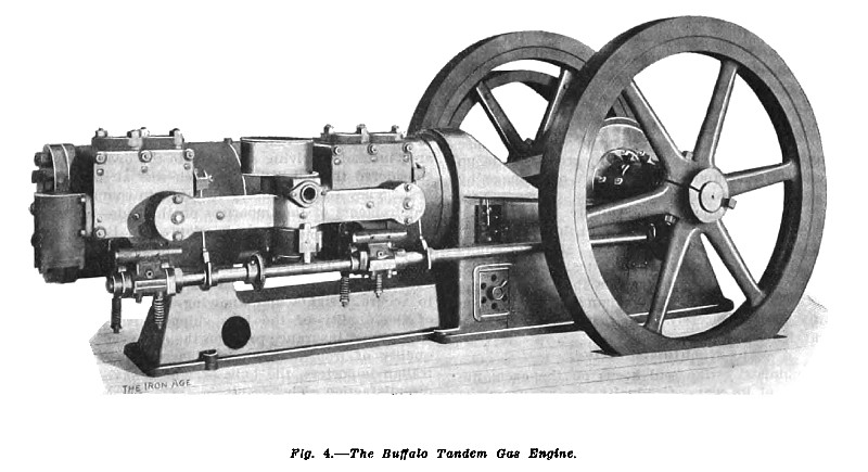
The Buffalo Tandem Gas Engine.
The Alberger Company of Buffalo exhibit one of their Buffalo tandem gas engines in the center court of the Machinery Building. It is belted to a Roots rotary pump, and in order to perform this work the engine is loaded to 122 brake horse-power, this load being carried daily from 10 a.m. to 10.30 p.m. The engine is operated with natural gas and is rated at 125 brake horse-power. It is of the two-cylinder type, with the single acting cylinders arranged horizontally in tandem, giving it an appearance similar to a tandem steam engine. The bore of the cylinders is 17 inches, the stroke is 19 inches and the speed of the engine is 190 revolutions per minute. The engine has an exceptionally strong and substantial appearance, and operates with the steadiness of a steam engine, and without any vibration. The manufacturers have realized that the steam engine has met with universal use because of its reliability and adaptability to meet without trouble largely varying conditions of load and service. It has therefore been their main object to place on the market a gas engine which comprises these features of the steam engine, and in addition furnishes an exceptionally economical source of power.
The cylinders are cast of hard grained iron, and are thoroughly water jacketed and in such a manner as to render it impossible for water or air to become pocketed in the jackets. The frame is a heavy box type casting, strongly braced, and has great rigidity. The material is so disposed between the main bearings and the cylinder yoke that the working stress is carried in straight lines. The frame is extended under the cylinders to a pedestal support, designed to carry only the weight of the cylinders. The working stress from the rear cylinder is communicated directly through the metal to the front cylinder in straight lines to the main bearings. The main bearings, which are of remarkably generous proportions, are split at an angle so that the rigid frame and not the cap is presented to the thrust. The bearings are lined with genuine Babbitt metal, securely anchored, thoroughly hammered and accurately bored. The fly wheels on this engine are 78 inches in diameter, with a face of 6 inches. The driving pulley is bolted to the spokes of one fly wheel.
The crank shaft is 6½ inches in diameter by 6 feet 2¼ inches long. it is a one-piece open hearth homogeneous steel forging, to which are secured two cast iron counter weight disks. These disks are so proportioned as to secure a correct running balance of the engine. The connecting rod is an open hearth steel forging of rectangular cross section, having marine type crank pin box. The method of attachment to the piston permits easy removal of the rod when desired.
The pistons are single acting and are carefully fitted with special cast iron self-adjusting packing rings. Undue heating of the pistons is prevented by reason of one side of each piston being exposed to the atmosphere. Simply removing the rear cylinder head allows the reciprocating pad to be readily removed for examination and cleaning.
On one side of each cylinder is securely bolted a valve chest, which contains the admission valve and the exhaust valve necessary for the operation of that cylinder. From the lower side of the valve chests, and integral with them, projects the cam shaft hanger. On the top of each chest are two hand hole covers, one being over the admission valve and one over the exhaust valve. These covers are easily removed; one is equipped with relief valve and the other is tapped for indicator connection. The admission and exhaust valves are of the vertical poppet type and positively actuated.
The cams operating the valve mechanism are rotated upon a 2½-inch diameter steel shaft conveniently placed along one side and lengthwise of the engine. This cam shaft is firmly supported by three bearings placed close to the point from which power is delivered to or by the side shaft. The speed of the can shaft is one-half the speed of the engine, and is driven by a pair of cut helical gears.
The engine is operated on the standard four-stroke cycle, the cycle comprising admission, compression, expansion or working, and exhaust strokes, continuously repeated in the order named in each cylinder. The periods, however, are not simultaneous in the cylinders, but are spaced one revolution apart. Thus, if the expansion or working stroke is occurring in one cylinder admission is occurring in the other cylinder; if compression is occurring in one cylinder the exhaust gases are being expelled from the other cylinder during the same stroke. Taking the two cylinders in conjunction, a working stroke occurs for each revolution of the engine. This equal spacing of the working impulses results in smoothness of operation and freedom from vibration.
One of the distinctive features of this engine is its governing device. The gas and air are mixed by suction and intermingling in economical and proper proportions.
Before entering the cylinders, however, this mixture or charge must pass through a cut off valve, which permits the passage of the charge in an amount or volume accurately graded to the load on the engine.
A practically free suction of the charge to the cylinders is therefore permitted during the time the valve is open, avoiding throttling or wire drawing of the charge and consequent friction, and maintaining the exact proportions or quality of the charge through the variations -of the load. The intensity or force of the power impulses, following precisely the action of the governor, gives close regulation.
In consequence of these characteristics the engine is exceptionally applicable to the economical generation of electric current, responding promptly to varying conditions of load on the generator, and for electric lighting, .giving steady and flickerless lights.
The relative proportions of the constituents of the charge or mixture may be varied through the widest possible range by the simple taming of a thumbscrew; the .screw adjustment also permits the most minute variations with micrometer accuracy. In other words, the -constituents of the charge may be varied to suit not only the particular gas used in any case, but the adjustment may be made to suit any of the various fuel gases, whether natural gas, illuminating gas, producer gas, furnace gas, gasoline, &c.
The combustible charge is ignited by an electric spark massing between two points when their contact is suddenly broken by means of a trip. The igniters are very substantially and accurately constructed. The spark points are made of a practically indestructible alloy, which wears for years. The points are brazed on steel electrodes. The electrodes are held on a solid plug, bolted on the side of the valve chest, directly adjacent to the admission valve. This position of the sparking points in the path of the cool entering charges preserves them from the possible destructive effects of overheating. The plug can be readily removed and replaced; the joint is ground and requires no packing. The trip is actuated by a plain eccentric on the cam shaft.
The construction of this igniter is particularly original, in that the point of revolution at which ignition occurs may be instantly varied at will by the operator, either while the engine is at rest or in operation, and is definitely indicated for any setting of the igniters on an exposed dial. The most economical point of ignition may be determined by a reference to the gas meter. When starting the engine the igniter is set forward to a definite point, giving easy starting impulses and preventing reversal of the engine: when the engine is up to full speed the igniter is shifted back to a predetermined point for the best economical results.
The igniting current, when the engine is running, is supplied by a small dynamo, located on a bracket bolted to the side of the frame, being self-contained with the engine. When starting the engine the igniting current is supplied for a moment by cells. The demand on the cells is so short that they last indefinitely without renewals. The cells are enclosed within the engine frame, where they are secluded from liability to damage. The exhaust gases, before leaving the engine, are intimately mixed with the waste jacket water in a novel and effective manner, which instantly reduces the temperature and consequently the volume of the exhaust. The discharge of the exhaust to the atmosphere, instead of having the usual loud report, resembles the exhaust from a steam engine in quietness and appearance.
The lubrication of the cylinders and bearings is accomplished simply and effectively, glass body sight feed oil cups being used. The crank pin is oiled in a positive manner, the oil being fed from a stationary oil cup, and no wiper devices or movable oil cup are necessary.
It should be noted that the use of tandem cylinders has made possible a. design of exceptional compactness, in the convenient grouping of the admission and exhaust valves, the valve chests, the governor and mixing valve, water valve, gas valve, igniters and self-starter on one side of the engine. The concentration of these parts within practically one step of the operator will be readily appreciated by those who have had experience with other types of multiple cylinder engines. At present the Buffalo tandem gas engines are built in sizes ranging from 30 horse-power to 250 horse-power. |
|
 1901 A. H. Alberger Co., Buffalo Tandem Gas Engine
|
|