|
Title: |
1921 Article-Baker Brothers, #121 Drill Press |
|
Source: |
Machinery, V28, Oct 1921, pg. 156 |
|
Insert Date: |
6/14/2016 1:27:42 PM |
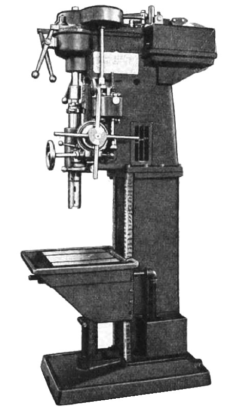
Baker Bros, Toledo, Ohio, have added the No. 121 single purpose and the No. 121 quick-change drilling machines to their line of products. These machines are adapted for driving drills ranging from % to 1% inches in diameter, and in the general lines of construction are somewhat similar to the No. 217 single-purpose and the N0. 314 flexible machines manufactured by the same concern. There are, however, a number of changes and improvements of design, the more important of which will be mentioned in the subsequent description. The No. 121 quick-change machine is shown in the accompanying illustration. The single purpose machine is similar to this, but the feed-box is provided minus the feed-change gears, shafts, etc. A single purpose machine can be converted into a quick-change type by the provision of the necessary shafts and gears, which are interchangeable so that they can be assembled without fitting.
Slip change-gears are furnished in addition to the sliding gears to increase the range of speeds, so as to assure the efficient operation of all sizes of drills. This provision also facilitates the efficient use of different sizes of taps. It will be seen that a cabinet is provided in the column to receive these slip change-gears. The introduction of slip change gears also provides different feeds from those formerly supplied, and so a different dial is provided to correspond with each set of slip change-gears. Attention is called to the convenient arrangement of all operating levers, which are not only centralized, but also located to enable the hands of the operator to move continuously from the highest position downward in shifting levers manipulated with either his right or left hand.
Another feature of the improved design is the casting of the bearing brackets for the tight and loose pulleys integral with the machine column, the pulleys being located directly behind the column. This arrangement is important when it is desired to set machines in gangs, as it brings the control levers on all machines within easy reach of the operator and saves floor space. Simultaneously with the throwing of the belt on the loose pulley, a cam-actuated brake is applied to the tight pulley to bring the machine to a stop quickly. A piston on the spindle rises into a cylinder as the counterbalanced spindle rises rapidly to the starting point after the feed has been tripped. By this means the spindle is quickly returned without occasioning any shock as it reaches the top of its upward movement.
Included in the table-elevating mechanism is a sleeve nut that slides in an auxiliary column. In adjusting the position of the table, the bolt which clamps this sleeve is loosened: then by clamping the table to the main column of the machine and turning the table-elevating crank, the sleeve may be raised or lowered. By tightening the sleeve-clamping bolts and loosening the table-clamping screws, the table is ready to be moved to any desired height. Attention is finally called to the fact that the speed change-gear box is made as a unit, which may be readily removed from the column. Ball and roller bearings are provided for the shafts in the speed-box. |
|
 1921 Baker Brothers, #121 Drill Press
|
|