|
Title: |
1921 Article-G. A. Gray Co., Iron Planer (Helical Geared Drive) |
|
Source: |
Machinery, V28, Dec 1921, pg. 285 |
|
Insert Date: |
6/19/2016 12:55:37 PM |
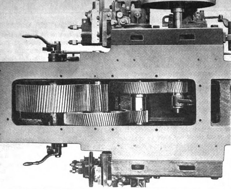
The table is driven by a system of helical gearing which produces a smooth and powerful drive. A properly designed pair of helical gears is stronger than a pair of spur gears of the same pitch and width of face for the following reasons: In the case of a spur gear, the load at a certain point of a tooth engagement is concentrated along a line at the tip of the tooth, and the leverage is practically equal to the depth of the tooth.
In the case of a helical tooth, the load comes on a line passing obliquely across the tooth face and the leverage of the force amounts to only one-half the depth of tooth. Further, the helical gear tooth centers engagement gradually, eliminating shock. In addition to their greater strength, helical gears give a continuous pitch-line rolling action, since there is always some point on the pitch circle where mating teeth of the gears are in actual contact.
The helical gearing in the Gray planer drive has a tooth form which is thicker at the root than teeth of the conventional form. This modification is said to increase the strength 40 per cent, eliminate interference, and reduce the angle of approach. It is while moving through part of the arc of approach that the so-called "stuttering" action takes place in gearing of the ordinary type. The angle of recess is purposely lengthened, however, because while a tooth is passing through the arc of recess the tooth friction tends to reduce instead of increase vibration. In the design of this gearing, use has not been made of stub teeth and large pressure angles, because while these features are of great advantage in certain kinds of work, the requirements of general planer service prohibit their successful use except for roughing and other service where gear chatter is not objectionable. The full-length tooth and low pressure angle of the special tooth form adopted in this gearing distribute the load among a greater number of teeth than would be the case with a larger pressure angle.
The gears dip into a reservoir of filtered oil so that the teeth are always covered with lubricant. This results in smooth action and long life of the gearing, because the oil film interposed between the teeth tends to cushion any shock that might be transmitted from one tooth to the other.
An objection to helical gearing sometimes raised is the fact that gears of this kind produce end thrusts. While such end thrusts may be eliminated by the use of herringbone gears, the Gray Co. contends that a better system of gearing with wider faces, greater strength, smoother action, and longer life may be obtained if helical gears are used and advantage is taken of the end thrusts to counteract the tool pressure. A planer normally operates with the tools feeding from right to left, the operating side of a planer always being the right-hand side, and the side thrust of these tools tends to push the work and the table toward the left. The teeth of the bull gear in the planer design under discussion are so cut that the end thrust which the gear produces on the table is about one-tenth of the driving force, thus practically balancing the side thrust of ordinary cutting tools; because of this design the planer table bears equally on all four faces of the guiding ways.
The bull gear does not tend to move endwise since the end thrust of the bull pinion balances that of the table rack. The remaining gears of the train are so disposed that each one partially balances the end thrust of another, leaving only a small end thrust which is taken care of by bronze washers supplied with oil by forced lubrication. Most planer work does not occupy the entire width of the planer, and for convenience is placed close to the operating side of the machine. It is, of course, desirable that the line of action of the force which drives the table rack should coincide as nearly as possible with the line of action of the cutting tools. The rack of this planer is, therefore, widened toward the operating side of the machine which brings the line of action of the forces in an advantageous position. |
|
 1921 G. A. Gray Co., Iron Planer (Helical Geared Drive)
|
|