|
Title: |
1921 Article-G. A. Gray Co., Iron Planer (Feeding Mechanism) |
|
Source: |
Machinery, V28, Dec 1921, pg. 286 |
|
Insert Date: |
6/21/2016 1:10:12 PM |
The "Cantalip" Feeding Mechanism
One of the greatest advances in lathe design was the development of the quick-change-gear system, and it is not too much to say that quick-change gearing has increased the production of the lathe from 20 to 30 per cent by making instantly available the feed best adapted for the work in hand. While the conventional friction-and-rack feed of the planer has undergone a great deal of refinement that has made it much more satisfactory and efficient than originally, many engineers consider the positive feeding and quick-changing devices employed in the lathe, boring mill, and milling machine to be still better in designing the feeding mechanism, the Gray Co. had in mind the following points:
1. The mechanism must be positive and not subject to slip or wear.
2. The mechanism must been closed so that chips and dirt cannot affect it.
3. The side-head feeds must be independent of the rail feeds.
4. The amount of feed must be instantly adjustable while the planer is operating.
5. The adjusting mechanism must indicate exactly the amount of feed for which it is set.
6. The direction of feed of the rail-heads must be instantly changeable.
7. The adjusting mechanism must be in a convenient and accessible position.
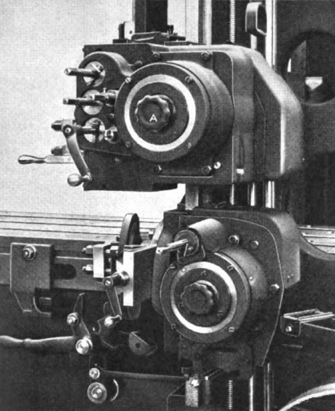
The design developed to meet these requirements is illustrated in Fig. 2. One of the intermediate shafts in the main drive is extended through the housing, and by means of a flexible coupling, drives a pair of bevel gears running in oil. From these gears there rises a vertical splined shaft which rotates alternately in either direction as the planer operates. This motion is transmitted to a ratchet mechanism on the cross-rail, so designed that pawl lifters projecting from the aluminum case which completely encloses the mechanism, strike upon stop-pins, one of which is fixed, while the other is adjustable. When one of the lifters strikes the corresponding stop-pin, the ratchet mechanism is automatically disengaged and the aluminum case brought to rest, remaining so until the vertical shaft which drives the mechanism reverses its direction with the reversal of the planer. The ratchet mechanism operates noiselessly, and all parts are lubricated by oil contained in the case and supplied through oil passages in the driving shaft. On the periphery of the case is pressed a large ring gear which transmits its motion to the gears on the feed-screws and feed-rod.
The ratchet box is enclosed in a cylindrical case which forms a gear guard and serves to support the feed-adjusting device, consisting of a circular plate in which a hole is broached for a sliding bolt. The bolt engages teeth cut in a nickel steel ring and is withdrawn from engagement by slightly turning knob A. Any further turning of the knob revolves the plate and its attached stop-pin to the desired position. When the knob is released, the bolt re-engages the teeth in the ring, and the plate and pin are locked firmly in place. Graduations on the disk indicate the amount of feed in thousandths of an inch. It will be seen from this description that only an instant is required to obtain any desired feed, which may be varied by multiples of 0.010 inch. The smallest feed obtainable is 0.010 inch and the largest 1.250 inches.
The side-head feed is independent of the rail-head feed, but is operated and adjusted in an identical manner. With this arrangement the side-head feed may be large while the rail-head feed is small, whereas with the conventional friction-and- rack feed, the side-head feed is necessarily equal to or less than the rail-head feed. The feed mechanism is provided with a safety device in the form of a small pin at the lower end of the vertical feed-shaft, which will shear without damaging the mechanism if the heads are fed together or any other accident results from carelessness or inattention on the part of the operator. The vertical shaft is hardened to receive the pin and it is but the work of a moment to replace the latter.
Developing the Rapid-Power Traverse
With the increased speed of cut permitted by the use of high-speed steel and the increased feed and depth of cut possible on modern machines, work is finished more rapid and a larger proportion of the time is expended in change tools and moving the heads from place to place. This c! for increased effort on the part of the workman, and a rat’ power traverse enables this work to be done without fatigue and in less than one-third of the time required if the if must be traversed by hand. For a power traverse to be of value, it must be so simple and easy of manipulation that no appreciable time is required to put it in motion. It should not be necessary to do anything beyond moving a single member controlling the part to be traversed. Otherwise, so much time is taken in the manipulation of the mechanism that little saving results from the increased speed of head movement. Above all things, it is important that a workman should not be required to perform a series of steps before moving a head, if a serious accident to the machine may occur when one of these steps is neglected. Accordingly, in designing the power traverse for the planer being described, the following points were borne in mind:
1. There must be only one handle for each movement required.
2. The movement of this handle m u s t automatically perform all the functions necessary to disengage the feed, e n g a g e the power-traverse mechanism, and energize the source of power.
3. The direction in which this handle is moved must correspond to the direction in which the head controlled by it is moved.
4. It must be possible to move any head in either direction while the planer is in operation.
5. The moving of a head must not disturb the operation of any other head.
6. No part of the rapid power-traverse mechanism should run when it is not being used.
7. The mechanism must not revolve the handles or the handle shafts on account of the danger involved.
8. A power traverse must be provided for the side-heads, where it is sometimes even more important and desirable than it is for the rail-heads.
In addition to the requirements stated in the foregoing, which are vital to the operation of the machine, a number of other requirements had to be met relative to the manufacture and assembly of the mechanism. The device must be simple and compact, or it cannot be placed in the limited space available in the side-heads. A number of designs which filled the operation requirements were unsatisfactory because they did not lend themselves to the system of unit assembly which finds so large a place in modern machine tool practice.
Operation of the Rapid Power-traverse Mechanism
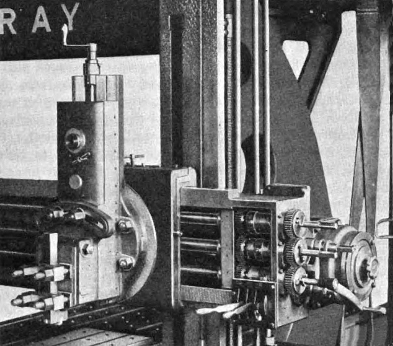
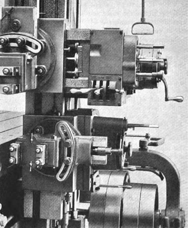
The design finally evolved is shown in the heading illustration and in Figs. 3 and 4. The mechanism is driven by an electric motor mounted on the top brace, which may be of either the alternating or the direct-current type. The motor receives its current through a reversible controller. A gear-box, also mounted on the top brace, contains the necessary reduction gears which run in oil and in addition serves to support the rail-elevating device. Power from the gear-box is transmitted to the power-traverse clutch mechanisms located at the end of the rail, and on the side-heads. The handles seen projecting from the power-traverse box at the end of the rail, and from the bottoms of the side-heads, are connected with rotary cylindrical cams which have an endwise motion and are concentric with the rail or side-head screws, as the case may be.
A movement of one of the handles rotates its cam and shifts it endwise, causing the unclutching of the corresponding screw from the feed mechanism md clutching it positively to the power-traverse gearing. The same movement causes the handle to engage and rotates collar, the movement of which is transmitted to the controller. The direction in which the handles are moved determines the direction in which the controller rotates, and hence governs the direction of rotation of the motor and if the head movement. When one handle is moved from neutral to the operating position, all other handles are automatically prevented from moving so that the mechanism cannot-be injured by carelessness on the part of the operator. The motor stands still except when the handles are moved. A lubricating system, which requires no attention except the filling of two reservoirs on the rail and one on each side-head every morning, carries oil to all parts of the power-traverse mechanism.
Rail Elevating and Clamping Devices
When the rail is clamped to the housings by means of a pair of cast-iron both the rail and clamps bearing the work. If the against ledges on the outside edge of the housing faces and drawn up by two bolts, in order to move the rail, it is necessary for the operator to take seven distinct steps as follows:
1. Loosen the two bolts on the right-hand clamp.
2. Walk around the planer.
3. Loosen the two bolts on the left-hand clamp.
4. Operate the lever controlling the elevating device while watching the height of the rail.
5. Clamp the two bolts on the left-hand clamp.
6. Walk around to the right-hand side.
7. Clamp the two bolts on the right-hand clamp.
In contrast to the foregoing the new Gray planer has a rail-elevating and a rail-clamping device, the operation of which involves only three simple steps that can all be performed without requiring the operator to move from his normal position. |
|
 1921 G. A. Gray Co., Iron Planer (Feeding Mechanism)
 1921 G. A. Gray Co., Iron Planer (Close-up View of Rapid Power-Traverse Mechanism)
 1921 G. A. Gray Co., Iron Planer (Feeding & Power Traverse Mechanism)
|
|