|
Title: |
1827 Article-Mason & Tyler, Turning Lathe |
|
Source: |
Journal of the Franklin Institute, V3, Mar 1827, pg. 186 & Plate 44 |
|
Insert Date: |
11/30/2016 8:10:06 PM |
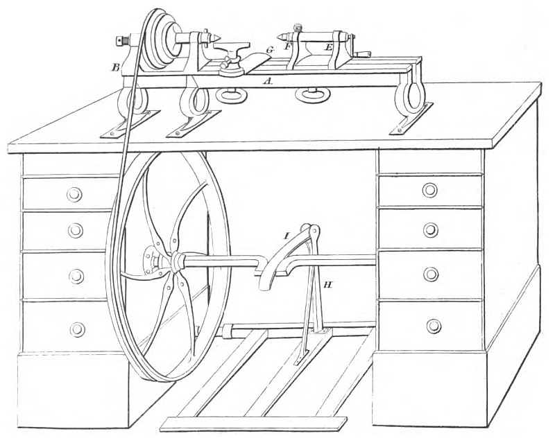
A description of the improved Turning Lathe, as made by Mason and Tyler, of this city.
At the second annual exhibition of the Franklin Institute, a turning lathe made by Mr. Rufus Tyler, excited much attention among those who were judges of that instrument, both on account of the perfection of the workmanship, and the improvements in its construction. In respect to the former, it might safely be compared with the most perfect productions of the workshops of England or France. The sliding parts, traversed with an equability and ease, which left nothing to be desired in that particular. The front centre, which, (as may be seen in the plate,) was a sliding bolt, might be used without the tightening screw, in turning steel, or other metals; and, in fact, the large and small lathes in Mason and Tyler's workshop, although provided with tightening screws, are generally used without them. The cast-steel screw by which this centre was moved, might be worked its whole length without the slightest shake, wabble, or inequality; the centering appeared to be absolutely perfect, and good workmen are well aware of the difficulty of attaining this high degree of accuracy. In constructing this lathe, Mr. Tyler availed himself, not only of his own experience, but of the improvements made by Messrs. Lukens, Mason, Clarke, Baldwin, and others among our best mechanicians. Simplicity of structure was particularly consulted, as the main object was to produce a lathe adapted to general use; it is represented, therefore, without those appendages which are designed for particular purposes only, such as guides for cutting screws, and eccentric and oval chucks; these, however, may, of course, be attached to it when desired.
The accompanying plate was engraved for Carey and Lea's edition of Nicholson's Mechanic; in which work, a description is also given of the turning apparatus of Maudslay, and of Smart, of London, which may be consulted for the manner of applying the lathe to certain particular uses. We have somewhat enlarged the description of Mr. Tyler's lathe, as we know that it will be acceptable to many of our readers.
A, The shears, of cast iron, with three feet, which serve to connect them firmly at a proper distance from each other, leaving the spaces between them unobstructed by cross bolts, and permitting the sliding head and rest to be taken out, without detaching their holdfasts.
B, The standing head, cast in the usual way.
E, The sliding head.
F, The front centre sliding bolt. This is a cylinder, sliding in a hollow cylinder, which is formed in the top of the sliding head. It is moved backwards and forwards, by means of a left-handed screw which passes into it.
G, The rest, cast with a groove underneath, to receive the head of its holdfast.
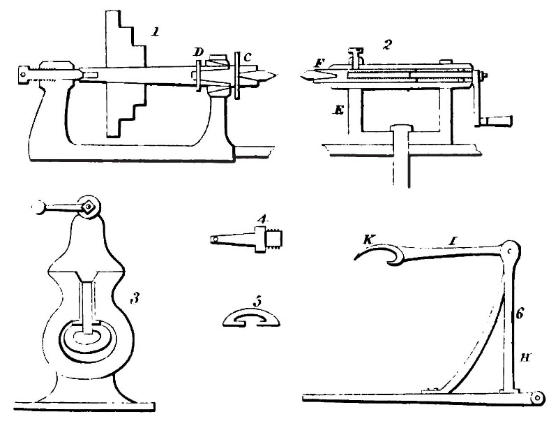
Fig. 1.—A section of the standing head, with its mandrel and drill chuck. The drill chuck C, is slightly conical, and is made fast in the mandrel by the key D.
The drill chuck has a conical hole, which in the figure is represented as containing a steel point. When drills are fitted into this hole, they are sufficiently firm for ordinary drilling, whilst they will generally turn round, from catching, or other extraordinary resistance, and thus be preserved from breaking.
The mandrel runs in a conical steel collar, which may be seen in the section.
The conical end of the back centre is truncated; it works against a hardened die let into the mandrel for that purpose, and sustains the pressure in drilling, &c. preventing that great increase of friction which is produced when the ordinary sharp angled cone is employed.
The conical end of the back centre is made somewhat more acute than the opening in the mandrel, which lessens the friction, and gives free admission to oil.
Fig 2.—E, A section of the sliding head. The front centre is represented as inserted into the bolt at F. At the opposite end is seen the left-handed screw, which is attached by a collar to the hollow cylinder of the head, with which it forms a case, which secures the bolt and screw from chips and dust.
Fig 3.—An end view of the shears and foot, with the sliding head and its holdfast.
The inner edges of the shears are beveled, and the sliding head has an angular piece screwed upon the bottom, which is nicely fitted into the bevel of the shears. Should any wearing take place, this is compensated by a thin piece of metal inserted between this bevel piece and the head.
Fig. 4.—A screw chuck, to be substituted for the drill chuck, in fig. 1.
Fig. 5.—A section of the bed of the rest, showing the manner in which the groove is formed.
Fig. 6.—An end view of the treadle, with its upright shaft H braced, and the pitman I, attached to it.
The form given to the pitman at K, where it fits on to the crank, admits of its disengaging itself when the treadle is obstructed, whilst it is securely retained in its place under ordinary circumstances.
A crank, with a short pitman, turns one of its dead points much more quickly than the other; in the arrangement of the crank in this lathe, advantage is taken of that peculiarity; the slower turn takes place at the bottom of the tread, and the too quick return upon the foot, which occurs in the common mode, is consequently obviated.
The lathe is most conveniently fixed in the way represented in the plate; that is, screwed to a table, which is supported at each end by a case with drawers, leaving a space between, for the wheel and treadle.
The wheel is of cast iron, with the arms curved to prevent their breaking from contraction, at the time of casting. The holes in the arms, are to admit of screws to affix a smaller wheel, when a slow motion is required.
In the old mode of fixing the treadles of lathes, the lever was of the third kind, and the crank was consequently made long. In the modern mode, the lever is of the second kind, and the crank must be proportionally short, or the rise for the foot will be too great.
This lathe is equally suitable to the use of the professed turner, and the amateur, as it is handsome, strong, easily adapted to various purposes, and not liable to get out of order. |
|
 1827 Mason & Tyler, Turning Lathe
 1827 Mason & Tyler, Turning Lathe
|
|