|
Title: |
1908 Article-H. W. Kearns & Co., Ltd., Boring & Surfacing Machine (Part 1) |
|
Source: |
The Engineer, 13 Mar 1908, pg. 277 |
|
Insert Date: |
1/12/2017 9:39:49 PM |
High Speed Boring Machine
Although commercial success in engineering factories is largely dependent on high cutting speeds with special machine tools, it is essential that the shops should be equipped with a certain proportion of tools which ae capable of being quickly adapted to a variety of operations. Such a machine is shown in the accompanying illustration, and although not entirely a new type—being based on Pearn’s patent—several improvements and modifications have been introduced, which are the results of extensive practical experience. The tool is equally useful for high-speed surfacing, boring, milling or drilling. The illustrations show one size of the machine, from which it will be observed that the pulley is driven by a wide belt and is mounted directly on the spindle between bearings. This eliminates driving through gearing for the high speeds required in drilling and milling. For heavier duty and slower speeds, however, spur gearing is brought into use, as will be mentioned later. Fig. 1 represents a side and end elevation of the machine; Fig. 2 shows the surfacing head and tool slide traveling towards the centre, and when this is completed, the movement of a lever will cause the slide to travel outwards and finish the work on a broad transverse. Provision is made against overrunning and the slide can be operated by hand motion, which is disengaged when the power feed is in engagement. As stated above, power is transmitted to the spindle by means of a wide endless belt, which makes a large arc of contact with the driving pulley. This is seen in the end view, Fig. 1. The belt can be quickly adjusted to any required degree of tension by means of the tightening pulley above. When drilling or boring small diameters, the main driving pulley is directly connected to the spindle by means of a locking pin. This is a very important feature, as it enables the machine to work at high speed without the intervention of any tooth gearing whatever. For operating on work of larger diameter, motion is transmitted from the gearing to the chuck or face plate by means of an external pinion meshing with a spur ring, as shown in Fig. 2. In this respect, modern design in heavy lathes has been adopted, and the spindle is relieved of torsional stress. The bearings of the spindle are kept as far apart as possible, so that the steadiness can be relied upon in snout-boring operations. The front bearing has a conical neck of large diameter, with adjustment for end thrust and wear. The head can be moved vertically on the upright slide by means of a cone friction clutch and bevel gear operated by power, while the large hand wheel shown provides for fine hand adjustments. Wear on this slide is compensated for by means of a wedge strip acting on a narrow guide, and of easy access.
The main table can be caused to travel longitudinally along the bed by either hand or power, the rapid power traverse being operated by a hand lever in a convenient position at the base of the upright. The transverse travel is effected by hand, but the power motions can be fitted if desired. The table may be also provided with a special spacing arrangement for boring holes at definite centres by using simple length gauges, thus rendering jigs unnecessary, while a detachable square turntable enables the machine to operate on four sides of the work at one setting.
The bed is of box section supported by cabinet feet, and at the driving end carries the upright and vertical sliding head, which are placed so that the centre of the spindle does not coincide with the centre lie of the bed. The object of this arrangement is to give effect of increased width of bed, the tendency of lift the work by the cutting action being counteracted by the increased leverage of the tables thus obtained. The machine is fitted with an improved feed mechanism. The semi-automatic machines have four rates of speed for drilling and boring, while the fully automatic machines have eight rates of speed for drilling, boring, surfacing, and milling in all directions. All the feeds are positive and capable of changing and reversing instantly. The feed mechanism is placed at the foot of the upright within easy reach an in full view of the attendant. A safety arrangement consisting of a friction plate is also overrunning. The whole mechanism is self-contained, requiring no change wheels, the full range of speeds being available by manipulation of the levers. These levers are marked to show their various functions.
For driving the machines, three methods are available—first, by four-speed cone and countershaft; secondly, by single belt from the line-shaft and a special speed-changing device; thirdly, by electric motor. The machine illustrated has the second system, the device being housing in the cabinet at the base of the upright. All changes are effected by the two levers shown. These, in conjunction with a friction clutch on the first motion shaft, give the necessary changes and, the levers interlocking, no two speeds can be in engagement at the same time. The boring bar stay is carried on a sliding saddle, which can be secured in any position on the bed. The stay has a vertical travel by hand, and can be locked in position. If desired, the stay can be placed on the tables, with which it will then travel, reducing the distance between boring bar supports.
It is not possible here to describe the various kinds of work to which the machine can be applied, but the application shown in Fig. 5 is interesting. The four pairs of cylinders are secured in a revolving jig placed on the table, and the jig thus takes the place of the detachable turntable. In this way the rough work on all cylinders is completed before finishing cuts are begun, and the heat engendered in the cutting is allowed to subside before the finishing are taken, while the machine is kept in constant operation.
The machine is built in accordance with Pearn’s 1907 patent, in four sizes, by H. W. Kearns and Co., Limited, Broadheath, near Manchester.
Courtesy Grace's Guide |
|
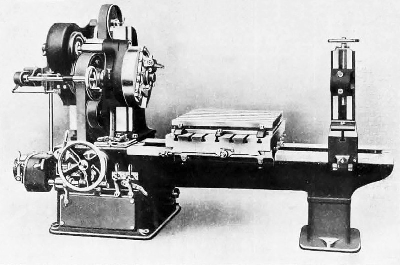 1908 H. W. Kearns & Co., Ltd., Boring & Surfacing Machine
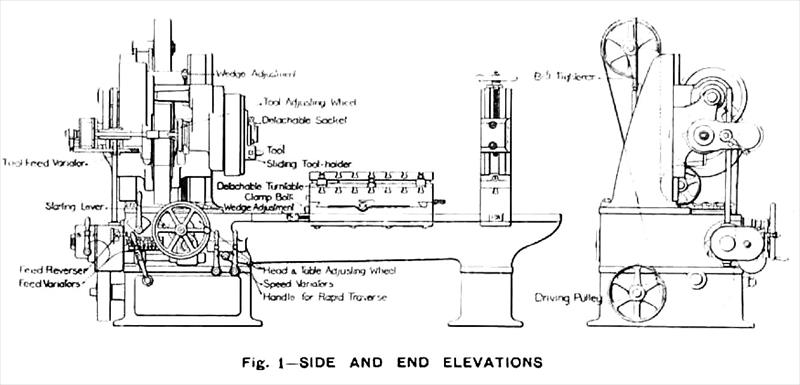 1908 H. W. Kearns & Co., Ltd., Boring & Surfacing Machine (Side & End Elevation)
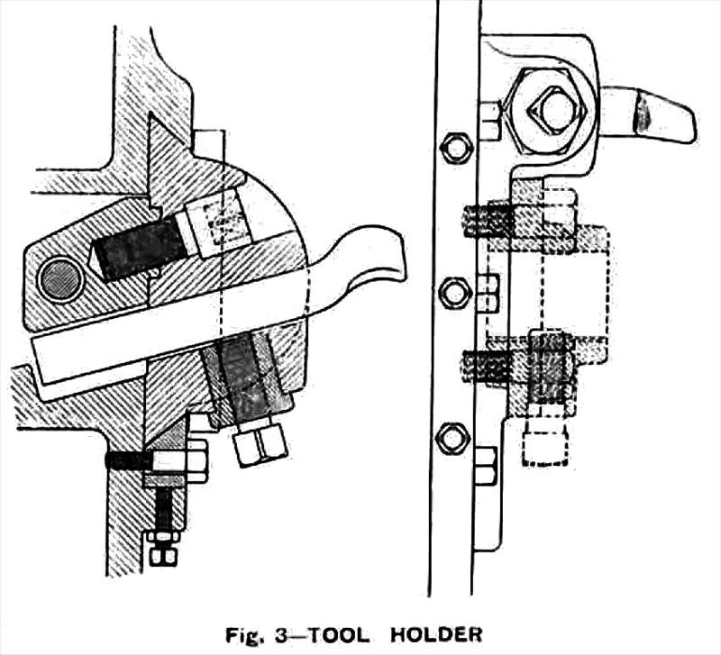 1908 H. W. Kearns & Co., Ltd., Boring & Surfacing Machine (Tool Holder)
|
|