|
Title: |
1860 Article-I. & R. Blackburn, Steam Traction Engine |
|
Source: |
The Engineer, V9, 13 Jan 1860, pg. 24 |
|
Insert Date: |
3/6/2017 9:53:21 PM |
Blackburn’s Steam Traction Engine
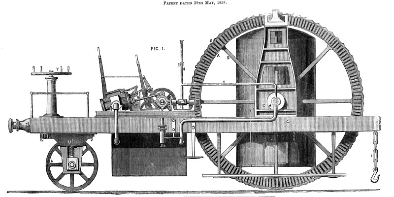
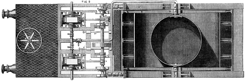
Fig. 1 is a side elevation, and Fig. 2 a plan of the locomotive or traction engine, constructed according to the invention of I. and R. Blackburn, of Long Eaton, Derby. A, A, is the large traveling drum, which is connected to trunnions A1, A1, by means of arms or spokes B, B, meeting in the central bosses B1, B1, through which the trunnions A1, A1, pass. The extremities a1, a1, of the trunnions pass through and support the frames C, C, to which are firmly secured the longitudinal beams C1, C1, on which the engine rests. The beams C1, C1, are strengthened with iron plates, and the drum A is strengthened by T-rings E, E, which pass entirely round it. The boiler E1 is supported by the inner ends of the trunnions, as shown in Fig. 2. The surface of the drum is composed of corrugated metal plates D, D, the spaces formed by the corrugations being filled in by timber G, G, in order to strengthen the corrugations and prevent them from collapsing; H, H, are bevel toothed wheels, bevel pinions I, I, gear, which cause the drum to revolve, as will be hereafter described; E1 is a boiler, which is supported upon trunnions A1, A1, in the middle of the frame; K is a pipe by which steam is led through the trunnion A1 to the cylinders L, L, of the engines; M, M, are the piston rods, which are joined to the cranks N, N, that drive the main shaft O, which carries at its ends bevel wheels P, P, that gear into the bevel wheels Q, Q1, which communicate rotary motion to the bevel pinions I,I, which gear into the toothed wheel attached to the traveling drum, and so cause it to revolve; R, R, are clutches provided with hand levers R1, R1, for throwing the pinions I, I, in and out of gear in order that the engine may be employed for other purposes than driving the drum; S is a pipe leading to a gauge S1, for indicating the height of water in the boiler E1; T is a foot-plate or platform, which is supported by the main frame C1 and the guide wheel U. In addition to this guide wheel, a roller or cylinder is used when travelling over soft land. This guide wheel is connected by a frame U1 with a vertical shaft that carries a cog-wheel V, inti which a pinion W gears. This pinion is attached to a vertical shaft X, which carries a hand-wheel Y, by which the whole machine is guided. The boiler E1 is supplied with water through the trunnion A1, opposite to that which supplies the cylinders with steam; Z is a water tank, which receives the steam from the exhaust, and contains a supply of water for the boiler. Z1 is a coupling chain for connecting implements of culture or other apparatus to the engine. |
|
 1860 I. & R. Blackburn, Steam Traction Engine
 1860 I. & R. Blackburn, Steam Traction Engine (Top View)
|
|