|
Title: |
1877 Article-Walker Bros., Scroll Saw |
|
Source: |
Scientific American, V37, 13 Oct 1877, pg. 227 |
|
Insert Date: |
4/13/2017 1:22:41 PM |
Workers in wood are generally aware that while the band saw is excellently suited for outside work, it is not so for inside cutting or perforated work. The jig saw, on the other hand, is adapted to both, and for the latter variety especially, owing to the facility with which its blade can be detached or unhooked and passed through the holes made in the piece to be sawed. On its capabilities in this particular are based the clams of superior economy usually advanced for the jig or scroll saw.
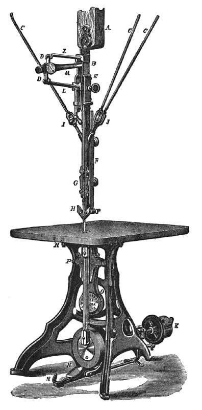
A new machine of this description is represented in the accompanying illustration. It is designed for general use on medium or fine work in hard or soft wood. It is durably constructed, and is provided with convenient means for the adjustment of all its parts.
As the straining device for the blade is one of the most important features in the construction of the scroll saw, special attention may be directed to the ingenious arrangement herein embodied. The object is to produce an even tension on the blade at all points of the stroke, and to enable the strain to be varied at pleasure. Springs, L, links, D, and lever, M, are attached to a casting that may be moved up or down the standard, B, for blades of different lengths. More or less strain may be imparted by turning the hand nut, I, so moving the lower spring, L. As the lever, M. travels on its upward or downward stroke, it throws the supports of the limbs, D D, forward and backward; in this way, the lever tension of the blade is maintained. The links, D. are attached to the ends of the springs and lever so as to roll on their points of contact or bearing surfaces, thus reducing friction of the working parts. The upper and lower fastenings for the saw blade are made to fit any thickness, and the blade can be quickly changed for perforated work without raising and lowering the upper slides or hold down, F. The lower slides, P, have a parallel adjustment, and are set up for wear by simply turning one screw, P, at the sides of each slide
A small rotary blower, O, attached to the frame under the table and driven by a pulley on the balance wheel shaft, forces a blast of air against the sawdust as it comes from the blade, keeping the slides free from dust, preventing absorption of the oil in the lower slide and guides, and preventing the noise and heat so common in slides when running loose and dry. A rubber tube, not shown in the engraving, is attached to the blower and conducts the air above, keeping the sawdust from the working lines of the sawyer.
The table is made of wood or iron, as preferred, and the filling around the saw blade may be of wood or of hardened steel. The latter is kept in place and adjusted by the screws, R, in front of the table. The hold down, F, and the slides, G, may be adjusted independent of each other for thickness of stuff or length of blade, and the back and side guide, H, removed, when not in use, for long or narrow blades. The lower slides, P, may also be set up for wear and kept parallel without trouble and loss of time. The saw is started and stopped ... the foot of the operator on the rod and brake, N, and the belt shifter, K—another important improvement —may be set for the belt in any direction. All the parts are well made and fitted, and guaranteed in every respect. The pulleys are 6 inches’ diameter by 3 inches face, and should make from 900 to 1,050 revolutions per minute. Patented May 27, 1873. For further information address the manufacturers, Messrs. Walker Bros., 73 and 75 Laurel |
|
 1877 Walker Bros., Scroll Saw
|
|