|
Title: |
1851 Article-William Bushnell, Metal Drill |
|
Source: |
Scientific American, 18 Oct, 1851, pg. 33 |
|
Insert Date: |
4/13/2017 8:17:21 PM |
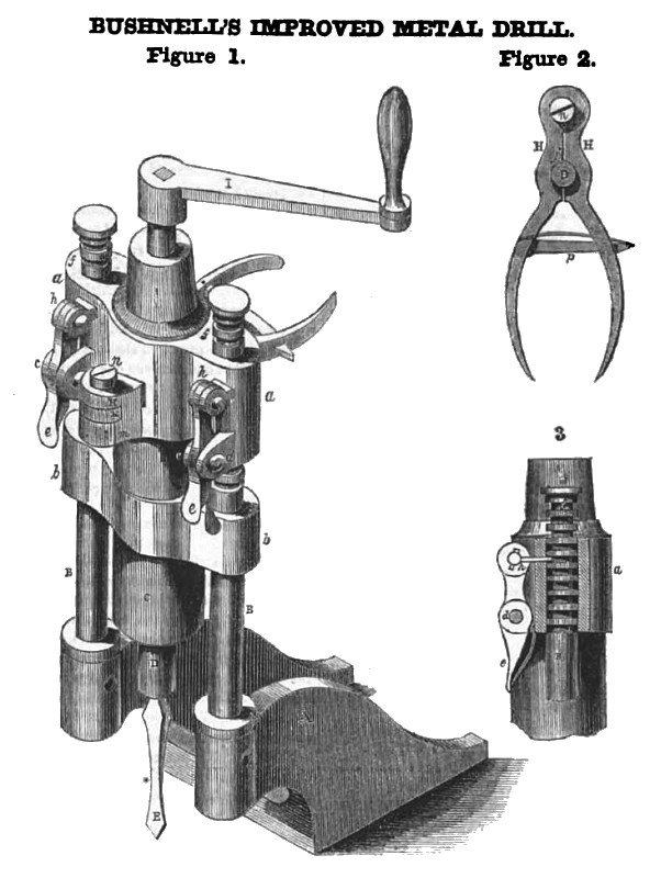
The accompanying engravings represent an improvement in drilling machines, invented by Mr. William Bushnell, of this city, who has taken measures so secure a patent for the same. A neat working model of this machine is exhibited in the machine room of the Fair, where we saw it operate with great satisfaction.
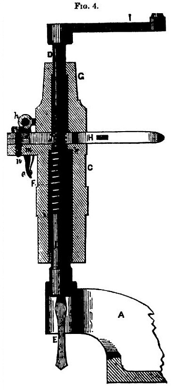
Figure 1 is a perspective view; Figure 2 is vertical section, of the standards, to which the base plate is connected. Figure 4 is a vertical section, showing the drill with the tension spring, and the box through which the spindle of the drill passes. The same letters refer to like parts.
A is the base or foot plate; B B are its two movable rods or standards, forming the guide frame for carrying the adjustable head, which consists of a hollow cylinder, C, having two tubular side guides, a b, for the standards. In front of the upper tubes, n n. is a pair of small lugs, C C, through which are inserted a pin, d, which is the fulcrum of the catch lever, e(one for each tube). Fig. 3 shows the catch, h, and f represents the grooves in the standard, B. These standards can he raised or lowered at will by pressing on the ends of the levers, e e, throwing out the catches. h h, when the standards, B B, can then be pushed up or down in their tubes, a b. The catches, h h, hold them in the desired position. There is a small spring under each lever, e, which tends to force the catch, h, into the notch or groove of B. D is the drill with a socket at its lower end. F is the drill tool; j is a screw cut on the drill spindle and fitting into the upper end of the cylinder, C. below the shoulder, G, (fig. 4). In the cylinder, C, is an enlarged space for the helical spring, F, which coils around the spindle, resting below on its shoulder, i, and bearing above against the shoulder, k, of the cylinder. I is the handle.
The nippers pass through and act in the adjustable head. The head of them is secured in the arm, m, (fig. 1) by the pin, n, which forms an axis for the arms H, H, to act on. Embracing the spindle D, (fig. 2) each side of the nippers is cut with a thread, which serves for a nut in which the screw, j, (fig. 4) of the spindle works. p is a spring which catches into an opening in one of the arms, H, and holds the arms together when they are closed as a nut around the screw of the drill spindle. The nippers are represented as closed in fig. 2.
Operation—The work being placed under the drill tool, and the machine being placed at its work, it is necessary to adjust the spring to give a suitable pressure to the drill stock; this is done by closing the nippers on the screw, j, until the spring, F, is sufficiently contracted, when the adjustable head is brought to a suitable position on the guide standards, B B; the nippers are then opened, and the drill spindle left free. The drill stock is then turned by the handle, I, and the expansion of the spring then gives the necessary pressure to the drill. When the hole is drilled to the requisite depth, the nippers are closed, and the spindle turned in the contrary direction, to raise it. The adjustable head can be set at once to bore any number of holes of the same depth, but it has to be changed for holes of varying depths.
The nature of this improvement, and its claim, consist in the combination of the helical spring, and the nippers, and the screw on the spindle, by which the pressure is controlled, and the drill stock operated in a most efficient and beautiful manner, as will readily be appreciated by any reader who pays proper attention to our description, and carefully examines the illustrative engravings.
We sincerely request those who wish such a drill as this, to examine and re-examine it. We do not wish to say it is good because it is here illustrated, but let it be inspected and judged upon its working merits. Orders will be received for it at this office. Price $25. |
|
 1851 William Bushnell, Metal Drill
 1851 William Bushnell, Metal Drill (Sectional View)
|
|