|
Title: |
1872 Article-Willaim A.Harris Steam Engine Co., Corliss Steam Engine |
|
Source: |
Manufacturer & Builder, V 4, May 1872, pg. 109 |
|
Insert Date: |
7/1/2017 8:26:36 PM |
The Harris-Corliss Steam-Engine
AMONG the many novelties and improvements which daily come under our notice, it is rarely that we find any of such importance as those which distinguish the Harris steam-engine from all others. What are these improvements? the reader not posted in this matter will undoubtedly ask. They are chiefly, economy of fuel, gaining 25 to 40 per cent over the best engines yet exhibited; regularity of speed; easy accessibility of all the parts; superior mechanical construction; besides many others of equal value. Among the main features of these many improvements, and one of the most valuable, is that one simple eccentric moves all the valves, so that no complicated gearing need be used, and that the same valve admits and cuts of the steam supply. These valves are represented in our third figure, and are worked like stop-cocks by the simple turning of the stems seen at the right. The way in which they are applied to the cylinder is represented in Fig. 4, which is a longitudinal section of cylinder, piston, and valves. The steam is admitted in the top, and passes alternately to the right and left, through the valves A and B, at each side of the piston, while the same escapes below at C and D. The peculiar form of the steam-valves is seen in A, Fig. 3, where its cross section is seen at the left. B, Fig. 3, represents the exhaust valve with cross section. The position of the valves in Fig. 4 shows that the piston is moving to the left, and at the same time how the exhaust-valve at C gives the full opening of the part to the escaping steam. It is evident that by this system the valves may be opened and shut very quickly and with slight friction, thus requiring a minimum of power, and also that the opening and closing may be regulated at the right time, so as to take the place of separate cut-off valves. The way in which this is accomplished is seen in our second figure, and is so original that it has drawn peculiar attention abroad. It consists of a wrist-plate placed in front of the cylinder, to which an oscillating motion is given by a single eccentric. At four points of the circumference of this wrist-plate, short levers are attached by rods, _ to which the valves A B C and D, Fig. 4, are turned. The connection of the lower rods, which work the exhaust-valves, is permanent, but the two upper rods working the steam-valves have a variable connection with the levels of these valves, which is regulated by the action of the governor, and which may be set to not earlier or later during the stroke of the piston, as may be required This, when detached, leaves the valve free to be closed quickly, for cutting 03 the steam, by a weight suspended by a rod from another lever on the valve-stem, and working in a dash-pot below the floor. The connection of the two upper wrist-plate rods with the levers of the steam-valves is made by means of a hook on the upper side of the lower branch of what is termed a " crab-claw." This is jointed to the rod, and the detachment of this crab-claw from the valve-lever is obtained by means of a cam-like projection or stop on a lever which oscillates on the valve-stem bushing, and is connected with the governor. The rise and fall of the governor varies the position of this stop, so as to make it act on the upper branch of the crab-claw, and depresses it so as to cause the disconnection of its hook from the valve lever and the liberation of the valve earlier or later in the stroke of the piston as required. The steam-valves are therefore subjected to the regulating action of the governor, upon which no work is thrown as it has merely to turn the levers and stops, and hence is very sensitive and quick in its action to regulate the constantly varying demands made. Even, in case the governor by accident failed to operate, and the engine was in danger of "running away," a very ingenious stop motion is provided, consisting of a pin screwed in the collar of each of the levers, through which the governor acts. The moment, therefore, the latter ceases to work, the pins come in such a position as to prevent the hooking on of the “ crab-claw,” when the steam valves do not open, and the engine, in place of “ running away," will stop.
It is evident how, by different ways of attaching the connecting rods to the wrist-plate, the motion of the exhaust valve may be made sudden, how they may be given a greater travel, and how the motion of the steam-valves may be made gradual, the amount of their travel regulated as desired, and also how, all their moving parts being outside and visible to the eye, any derangement can be seen at once and easily remedied.
In regard to the practical working of these engines, besides the great number now in operation in many establishments, we recall one we saw at the American Institute Fair in New-York, in 1869, which had a cylinder of 16 inches bore, and 42 inches stroke, and which gained the admiration of every expert. It was awarded the first premium for best results in net effective power; but by a very strange action on the part of the experts who were to judge about the engines in competition, an attempt was made to measure the amount of water or steam consumed, and not the amount of coal burned. Now, economy of water is only of secondary importance, while economy of coal is the main merit of a steam-engine, so that such action can only be explained by the fact that in economy of coal the Corliss engine is ahead of all competition. The experts who made the trials, in not testing this main point, made themselves liable to the suspicion that they did not desire to establish this feature in favor of the Corliss engine.
The manufacturer, Mr. W. A Harris, of Providence, R. I., we learn, entered a protest against this unfair mode of procedure, and has since published the points at issue in his pamphlet containing the description of his engine.
Condensing engines being much more complicated, and the different parts less accessible than those of the non-condensing kind, have thus far always proved troublesome to the engineer in case of accident. Mr. Harris has lately produced in his factory an improved condensing-engine, which he justly claims not to be excelled by any other in regard to convenience to the engineer, by reason of the perfect accessibility of every part. This same engine possesses some entirely new features in regard to the manner of introducing the water of condensation, the chief purpose of which is to prevent any vapor from reaching the air-pump. The latter incident is very objectionable; vapor being compressible or very elastic, and thus not solid like water, every change from water to vapor causes the pump to pound heavily.
In order to give the reader an idea of the present magnitude of the Harris-Corliss Steam-Engine Works, we will only mention that we saw there last week an immense fly-wheel for a four hundred horse steam engine, in process of manufacture. It was 24 feet in diameter, the rim had five feet face, and was one and a quarter inch thick. It has therefore a surface of not less than 375 square feet, and contains very near 40 cubic feet of iron, which, at the rate of 450 pounds per cubic foot, gives 18,000 pounds, or 9 tons for the rim alone, the whole fly-wheel weighing 30 tons. It is to run at a speed of 50 revolutions per minute; every particle of the 9 tons of material in the rim is then to move 50+75 =3750 feet per minute, which corresponds with 45 miles per hour; the velocity of an express train on a railroad. This combined with the other 21 tons of iron moving at a less velocity, is evidently an immense store of power, always ready to take momentum from the engine and give it back to we machinery to be moved. |
|
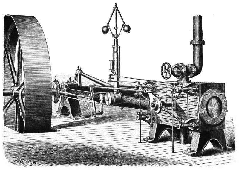 1872 Willaim A.Harris Steam Engine Co.,Corliss Steam Engine (Left Side)
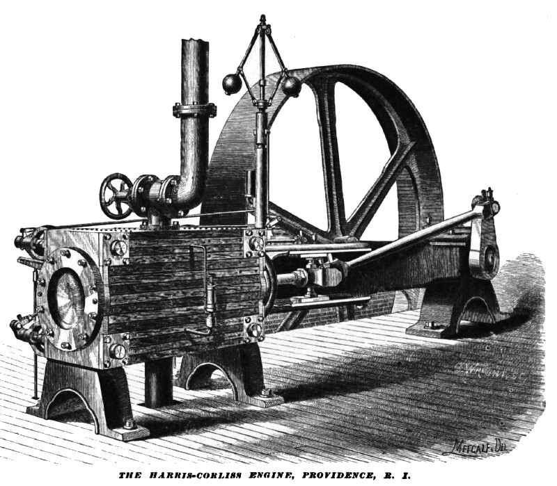 1872 Willaim A.Harris Steam Engine Co.,Corliss Steam Engine (Right Side)
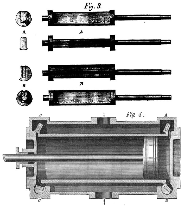 1872 Willaim A.Harris Steam Engine Co.,Corliss Steam Engine (Cylinder Section)
|
|