|
Title: |
Union Twist Drill Co., #2 & #3 Twist Drill Point Grinding Machines |
|
Source: |
Union Twist Drill Co. Catalogue L, pg. 259 |
|
Insert Date: |
10/25/2017 1:31:40 PM |
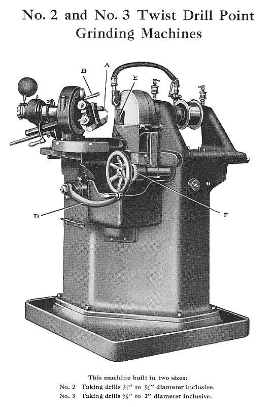
Capacity: This machine is built in two sizes, No. 2 taking drills 1/4” to 3/4” diameter inclusive, and No. 3 taking drills 5/8” to 2” diameter inclusive.
It will sharpen points of twist drills having right-hand spiral ?utes and two lips, and will grind same so that the cutting point will have lips that are the same length, with chisel point coming at the center of drill.
The drill is held by a two-jaw chuck “A,” operated by lever handle “B,” giving rapid movement of the chuck jaws, thus taking minimum amount of time in chucking the work. The chuck jaws are adjustable laterally so as to give same clearance angle for different diameters of drills. A graduated plate on the upper jaw gives the setting for different diameters. The jaws can be adjusted vertically so as to obtain different clearance angles as required. The machine is adjusted when assembled to give clearance angle of 12°, which has been found to be very satisfactory for general work.
The work spindle is carried in housing that is adjustable to give various included angles of drill points ranging from 90° to 118°. The machine is set when assembled to give 118° included angle of point, which has been found to be most efficient for general work.
The work spindle housing is carried by slide operated by hand lever “D” so that point of the drill is moved across face of the grinding wheel. This slide travels on hardened and ground roller bearings, which permits rapid traverse with minimum amount of effort.
Chuck Spindle: The chuck spindle front bearing is carried on hardened and ground steel rollers, and the rear bearing is carried in bronze box adjustable for wear and adjustable longitudinally so that chuck and spindle can be kept in correct position relative to the spindle boxes. The chuck spindle has rotary movement of about 110° and can be varied by setting adjustable screws.
Grinding Wheel: The grinding wheel “E” is of the ring type, 8" diameter, and is held by ?ange clamped to end of wheel spindle. The wheel head has adjustment of 4” to compensate for wear of wheel and allow moving wheel to correct position in relation to drill. A graduated collar “F” on adjusting screw provides means for moving wheel to same position for grinding both lips of the drill.
Wheel Spindle: The wheel spindle is hardened and ground, and runs in bronze boxes adjustable for wear.
Wet Grinding: All drills, both high speed and carbon, should be ground wet with an ample supply of water on work. A pump and tank with suitable piping is provided and supplies a sufficient ?ow of water to the wheel.
Water Guards: This machine is equipped with suitable water or
splash guards.
Wheel Truing: A diamond holder is clamped in the chuck jaws in the same manner as drill is clamped, and is traversed across the face of the Wheel. This insures cutting face of the wheel is parallel with the travel of the drills when they are held in the chuck.
Countershaft: Countershaft has tight and loose pulleys 10” diameter for 3” belt and should run 550 revolutions per minute.
Floor Space: 45” x 40” both machines.
Weight: No. 2, net 1,580 lbs. Boxed for shipment, 1,905 lbs.; No. 3, net 1,850 lbs. Boxed for shipment, 2,175 lbs.
Equipment: Two pairs of chuck jaws, grinding wheel, diamond, holder, wrenches, and countershaft.
Prices: On application. |
|
 Union Twist Drill Co., #2 & #3 Twist Drill Point Grinding Machines
|
|