|
Title: |
1920 Article-Conradson Machine Tool Co., #3 Plane Horizontal Milling Machine |
|
Source: |
Machinery Magazine, V23, Mar 1920, pg. 627 |
|
Insert Date: |
11/9/2017 8:11:08 PM |
C. M. Conradson of Eau Claire, Wis., la now building a No. 3 plain milling machine with single-pulley drive, which is illustrated and described herewith. It will be seen that, In a general way, the design of this machine follows established practice, except for the arrangement of the speed and feed gearing. It Is worthy of notice, however, that the machine is of exceptionally heavy construction. The duplex helical drive to the spindle is similar to that employed on the Conradson engine lathe. From the single driving pulley, which is 14 inches in diameter by 4 inches face width, power Is transmitted through heat-treated, chrome-nickel steel change-gears, which furnish the desired range of speeds. These gears are mounted in a cylindrical case which may be oscillated In such a way that engagement is made between either a worm and a worm-wheel keyed to the milling machine spindle or between a spiral pinion and a spiral gear keyed to the milling machine spindle. Thrust is taken by heavy-duty S.K.F. ball bearings.
This arrangement will be readily understood by reference to Fig. 3, which shows the mechanism in detail. It will be seen that driving pulley A is provided with a friction clutch If for engaging or disengaging the drive. This clutch is secured to shaft C that runs through the center of sleeve D. Carried at the left-hand end of shaft C are two sliding gears E and F which may be engaged with gears G and H to secure the first two speed changes. In either position of gears E and F, It will be seen that power is transmitted back through pinion I, which is keyed at the left-hand end of sleeve D. A third speed change is secured by sliding gears E and F to their extreme right-hand position, so that the clutch teeth on gear F engage direct with corresponding clutch teeth on pinion I. In this position, gears G and H will continue to revolve on the intermediate shaft, but they play no part in the transmission, as a direct high-speed drive is secured through sleeve D.
Near the center of sleeve D there are mounted two pinions J and K that mesh with sliding gears L and M on the lower shaft in the speed-box. Gear M may be engaged with pinion J, as shown, or the gears may be slid over to bring gear L into engagement with pinion K. Of course, it will be evident that the operation of sliding gears E and F is controlled by knob N, while operation of sliding gears L and M Is controlled by knob O, spring plungers being provided to enter notches in the rods that carry these knobs when the sliding gears are engaged In various positions. From shaft P In the speed-box, power is transmitted to the milling machine spindle by rocking the cylindrical speed-box to engage worm and wheel Q or spiral gears R, in the manner to which reference has already been made. The worm drive and the spiral gear drive are of widely different ratio, thus providing a greater range of spindle speeds than would otherwise be obtainable. Also, these helical gear drives furnish an exceptionally smooth transmission. Rocking of the speed-box to engage either the worm-wheel or spiral gear drive is controlled by a lever. This mechanism provides twelve changes of speed, covering a range of from 12 to 275 revolutions per minute, the changes being in practically geometrical progression.
Power for operating the feed mechanism is transmitted to the gear-box by means of a chain drive from sprocket T, Fig. 3. This feed-box is arranged with a cone of gears, the desired rate of feed being obtained by engaging the proper gear ratio with a driving key. Movement of this key is controlled by a screw, at the end of which is located dial A. Fig. 2, which is graduated to facilitate obtaining the desired rate of feed. This mechanism, in connection with compounding lever B, provides for securing sixteen changes of feed, ranging from ½ inch to 20 inches per minute. The feed can be changed while the machine is running, and the direct-reading index on dial A obviates the necessity of using tables. All feeds are instantly reversible.
This machine is arranged with a duplex helical drive to the spindle which, in connection with changes obtained from sliding gears in the speed-box. affords twelve speed changes from 12 to 275 revolutions per minute. This is the feature which represents marked departure from standard practice in the design of plain milling machines.
The over-arm is made of steel, and is 4¼ inches in diameter; this arm is clamped by wedges actuated by two levers that will be seen at the top of the machine. The maximum distance from the center of the spindle to the under-side of the arm is 6 3/8 inches, and the maximum distance from the end of the spindle to the arbor support is 25¼ inches. Two arbor supports are furnished, one of which supports the end of the arbor, and the other the middle. The front spindle bearing is 4¼ inches in diameter; and the spindle has a No. 11 taper hole and a 13/16 inch hole running through it. A faceplate forged integral with the spindle provides for driving face cutters.
The table is 12¾ by 63¼ inches in size, and the working surface is 12¾ by 53 inches in size. There are three 5/8 inch ,T-slots in the table, and the table feeds 34 inches in either direction. Each operating screw is provided with a graduated dial reading to 0.001 inch, and all hand-wheels are clutched. The maximum cross-feed is 10 inches, and the maximum vertical feed is 20 inches. The vise furnished with the machine has jaws 6 1/8 inches wide by 1 9/16 inch deep, and has a maximum opening of 3 5/8 inches. The floor space occupied by the machine is 96 inches in line with the spindle by 115 inches at right angles to the spindle; and the net weight of the machine is 4750 pounds. |
|
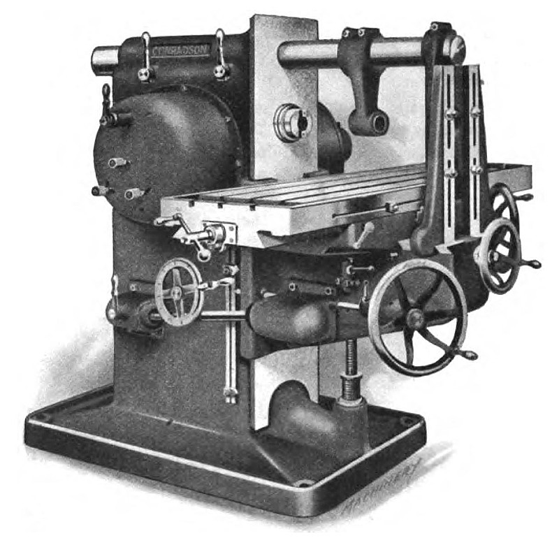 1920 Conradson Machine Tool Co., #3 Plane Horizontal Milling Machine
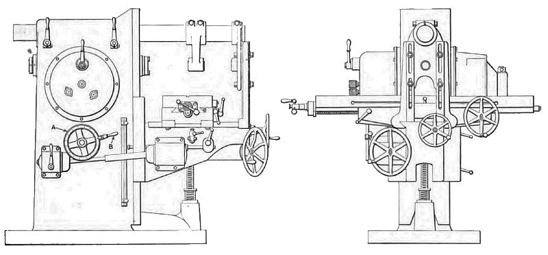 1920 Conradson Machine Tool Co., #3 Plane Horizontal Milling Machine (Front & Side Viewa)
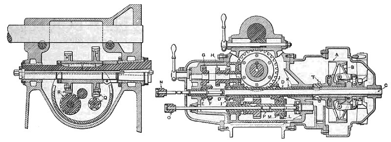 1920 Conradson Machine Tool Co., #3 Plane Horizontal Milling Machine (Speed Change Gear Box Cross-Se
|
|