|
Title: |
1864 Article-Thomas Whitfield & Co., Grimshaw's Atmospheric Hammer |
|
Source: |
Engineering, V18, 21 Oct, 1864, pg. 250 |
|
Insert Date: |
1/6/2018 9:02:22 PM |
In this invention of Mr. William Dakin Grimshaw, of Mitcham, he constructs the framework of the machine hollow and air-tight, so that it may be employed as a reservoir of compressed air, and at the back part of the bed plate he bolts or fixes a double-action air pump driven by a belt or by gearing. The piston of the air pump may be worked by a crank or other suitable contrivance. By the action of the air pump the hollow chambers in the framework of the machine are surcharged with compressed air (which may be rarefied or not at pleasure). The hammer head is fitted on to a piston rod connected to a piston working in an inverted cylinder, with similar arrangements to an ordinary steam cylinder, excepting in the construction of the cut-off. The slide valve has two port holes, and on the upper part of the valve there are two flaps or sliding blocks, which give the workman complete control over the hammer and enable him to regulate the blow at pleasure.
The hammer in either stationary or constructed upon a compound bed plate, so that it may be moved backward and forward, and be capable of striking any required blow upon any particular part of the anvil, or on a series of anvils, or of plating or bending heavy work, and performing such work as it has not been hitherto practicable for previously constructed mechanical hammers to execute. When the hammer is at rest the pump and air chambers may be employed as a blast or blower for the furnace with considerable advantage and economy. The blast may be used hot or cold, as may be required. The hammer in entirely under the control of the workman, both as to speed and the power of the blow. The speed may be varied from one to five hundred blows per minute, and its striking force from one to two thousand pounds, or in accordance with the constructed power of the machine it will do its work with considerably less consumption of power than is usually employed by steam hammers.
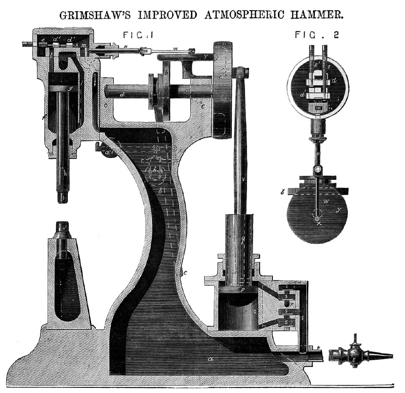
The manner in which this is to be performed will be clearly understood by referring to the figures and letters on the accompanying engraving, in which Fig.1 is a vertical section of one of the atmospheric hammers with a stationery bed, and Fig. 2 a plan of the slide valve and cutting-off flaps.
The main framework of the machine consists of the hollow bed a and hollow column b, both of which are used as reservoirs of air, and at the top of the column there are pedestals or bearings c for the driving shaft d to work in, the shaft being turned by the driving pulley e from any driving power; f represents the hammer cylinder; g, the hammer pistons; h, the hammer piston rod; i, the hammer head; j, the anvil block; k, the slide valve, having two apertures or port holes l, m, from back to face; n, the valve rod; o, the cylinder of the air pump; p, the piston or plunger or the air pump; q, the trunk or hollow piston rod; r, the valve box for the pump, having four valves s, there being a side pipe s¹ for conveying the air to the chamber u; t represents a pipe and cock communicating with the chamber a, which pipe and cock are for the purpose of tempering or regulating the pressure of the blow of the hammer by opening or shutting the cock so as to allow the air to escape or to keep it in, and when the hammer in not in use, the pipe and cock may be employed for conveying the blast of sir. The force of the blow of the hammer can also be tempered or regulated by moving the weight a3 on the lever of the safety valve b3. To the back of the driving pulley is fixed the crank pin u, which is connected to the pump piston p by the connecting rod v, so that as the driving pulley and crank pin revolve the piston shall work up and down according to the throw of the crank. The slide rod n is connected by a rod w to a crank pin x, fixed to the friction disc y working on a stud. On the crank shaft d there is a friction wheel b¹, held to the shaft by a key or feather, so that it can revolve with the shaft, and at the same time be moved to and fro when required by the clutch lever c¹, this friction wheel being for the purpose of giving the disc revolving motion when they are in contact with each other, the number of revolutions of the disc and to and fro motions of the slide valve k being in proportion to the greater or less distance the wheel is placed from the centre of the disc, which arrangements enable the speed of the slide valve, and consequently the speed of the hammer, to be varied with great facility. At the top of the slide valve there are two flaps or sliding blocks d¹ for cutting off the air at any particular given time, and thereby regulating the force of the blow of the hammer, these flaps being worked by the screws and rods e¹, or by levers, and the air passage from the air chambers to the valve in shown by the small arrows. When the hammer is placed upon a compound bed plate the anvil or anvils are detached from the framework, and the lower plate at the bottom of the chamber or reservoir is jointed by a bolt or swivel to a stationary foundation plate in order that the hammer may be turned to any required position. The formation of a reservoir for the compressed air in hollow and air-tight framework enables the machine to be very compact; but in cases where Mr. Grimshaw's improvements have to be adapted to old machines with solid framework, he employs one or more separate or distinct reservoirs for the compressed air; and although only one double-action pump is shown, it is evident that a series of pumps may be used, and also that the arrangements, dimensions, and strength of the machine may he varied, in order to adapt it for any description of work to be hammered. |
|
 1864 Thomas Whitfield & Co., Grimshaw's Atmospheric Hammer
|
|