|
Title: |
1913 Article-Augustine Automatic Rotary Engine Co., Rotary Steam Engine |
|
Source: |
Iron Age, 10 Jul 1913, pg. 71 |
|
Insert Date: |
3/27/2018 1:20:06 PM |
A Recent Automatic Rotary Engine
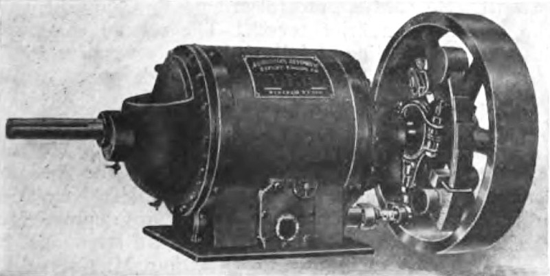
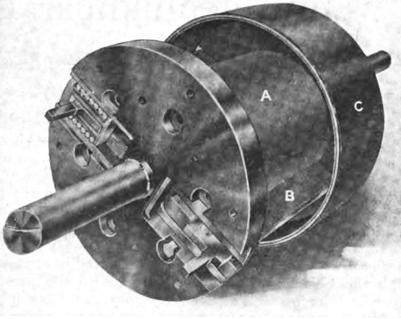
A new type of automatic rotary engine, for which the special features of compactness, absence of vibration and a low maintenance cost are claimed, has been developed by the Augustine Automatic Rotary Engine Company, 1862 Elmwood avenue, Buffalo, N. Y. These engines are built in a number of different sizes from 5 up to 150 hp., and, if desired, larger sizes can be built to order. They are designed for direct connection to electric generators, centrifugal pumps, fans and blowers, etc., as well as for work in machine shops and manufacturing plants. Some of the larger units are installed on separate foundations, the connection being made through a flexible coupling. Fig. 1 is an exterior view of the engine, while a view of the rotor, showing the sliding piston blades which are the special feature of the engine, is given in Fig. 2.
The rotating portion of the engine is made up of a cylindrical piston, A, Fig. 2, which carries the sliding blades B that move in and out on roller bearings in slots in the flanges. These blades are guided by arms, which bear in bronze bushings in the compensating balance rings. The flanges in which the sliding blades move are bolted fast to the pistons and have the telescopic disks C bolted to them. These disks set over the abutment, which is placed inside of the cylinder and in which the rotor moves. The piston, which is mounted in the abutment eccentrically with reference to the abutment bore, provides the means for the expansive working of the steam which is admitted through the pipe shown in the lower portion of Fig. 1. A Corliss type valve operated by a rocker arm and eccentric controls the admission of the steam, the position of the eccentric being regulated by an inertia shaft governor. The piston makes contact with the abutment on the priming pockets and is held there by the ring bearings, in which the shaft runs. As the blade passes the admission ports, which are located on one side of the central line of the bottom of the abutment, the admission valve is opened wide and steam is admitted behind the blade, forcing the piston forward until cut-off occurs, the exact point being controlled by the governor according to the load that is being carried. The steam then expands behind the blade, forcing the pistons forward until it reaches the exhaust port on the opposite side of the abutment when release occurs. The entire rotating member is carried on a shaft which runs in ring bearings located centrally with reference to the outer casing. The compensating balance rings are so arranged as to balance the centrifugal force of the blades, thus keeping the rotor steady at all times and moving the blades in and out of the grooves of the flanges so that they are kept bearing against the cylinder walls at all times with a packing strip along the edge to make a steam-tight joint.
Pressure is equalized between the cylinder and the inside of the telescopic disks C, through a series of small ports in the abutment and small check valves. The pockets on the outer periphery of the abutment are thus filled at all times with steam of the same pressure as that in the cylinder and this bearing against the inside of the telescopic disks gives a floating bearing.
In the automatic lubricating system which is used, oil is forced out through the pressure equalizing ports by centrifugal force and lubricates the running joint between the telescopic disks and the ribs on the abutment. The ends of these disks make a tongue and groove joint with the central rib running around the abutment, thus preventing leakage. The flanges bear against the ends of the abutment, making a running joint with packing rings. The piston, therefore, rotates inside the abutment, the flanges rotate against the ends of the abutment and the telescopic disks rotate in the space at the end of the abutment.
The endwise pressure is taken by the flanges which bear against the telescopic disks so that no pressure comes against the heads. As the steam is swept from the admission port around to the exhaust port without reversal, the result is a uniflow effect and the exhaust steam is not carried backward over the cylinder surfaces.
In a recent test made of one of these engines which was rated at 41 brake horse power, with steam at 100-lb. boiler pressure, 36½ lb. of steam per brake horsepower hour was consumed. The over-all dimensions of this engine were: length, 48 in.; diameter of casing, 17 in., and height, 20 in. |
|
 1913 Augustine Automatic Rotary Engine Co., Rotary Steam Engine
 1913 Augustine Automatic Rotary Engine Co., Rotary Steam Engine (Rotor)
|
|