|
Title: |
1901 Article-Coulter & McKenzie, The First Large Turret Lathe |
|
Source: |
Iron Age, V67, 23 May 1901, pg. 1 |
|
Insert Date: |
3/30/2021 1:26:18 PM |
Thinking that it might be of interest to you and your readers to hear something about the first real large turret lathe or turret machine that was ever built or used in this country, or, I believe, in any other country, I send the following account:
The inventing and marketing of this large machine went through the usual hardships and knockdowns of inventors generally, particularly in the years 1872 and 1873. At that time, we, Thomas Coulter and Hector McKenzie, were in the employ of the Howe Sewing Machine Company, and while there conceived the idea of making a machine that would take a wagon axle and finish it complete before being removed from the machine. Our means for carrying out such an undertaking were very limited. We hired a room in a convenient place and went at it nights after working hours. Some of the work we had to get done for us by machine shops.
The first machine had a wooden bed and legs, which were ornamented with beautiful scrolls. as shown by the accompanying engraving. After a long and hard struggle, we finally got it so that we could turn out an axle. Then we had to get it protected the cheapest way that we could, the result being the filing of a caveat in the Patent Office. Now is when our real troubles commenced. There was the machine, but where was the man or concern to give it a start. We had no money; who had was the question. There being several axle shops in Bridgeport we applied to them. One said “Yes, you can have room here to put it up, and if we like it we will talk to you about it.” We put it up, but they did not buy. They had excuses. We tried others. We had to explain that we could build a better one the next time, but it would cost more money. The result was that we could find no person to see it as we did, and we had no money to venture with the business of making them.
To show you what setbacks we received I will relate one instance: A prominent axle maker in New Haven was shown the machine. He seemed interested, and wanted some six months’ time, more or less, to decide. We granted his request, and waited anxiously the expiration of the time, but not hearing from him I thought it proper to call on him, and if necessary explain anything that he might wish to know. So off I went to New Haven, thinking that he must be interested: if not, hoping that I might be able to show him what could be done with such a machine.
I arrived at the house in due time; called for him at the door; was told he was in the hothouse among the flowers, and would I like to go and see him there. I gladly consented; was warmly received, &c.
I said that I had called to see what he had done about the axle machine. After a little while he said: “Well. sir, I would not give you 10 cents for your patent." I told him that I would take the papers and he could keep the 10 cents. I returned to Bridgeport with a heavy heart.
The machine had to be removed to Mr. McKenzie’s cellar, and was there about a year. In the meantime, I had changed my place of work to a regular machine shop, and while there my employer got a contract to make 10,000 sucker rods for pumping oil wells. He was changing his lathes, milling machines. and any other machines that he had in order to get out those joints and was thereby injuring his other business for the want of these tools. While watching all this going on it occurred to me that I could do all this work on my axle machine. I said to him, “What will you give me if I finish a machine and do this work for you?” The result was that the machine was dug up out of the cellar, set up. and was making sucker rods in quick order, even with the wooden bed.
This gave us new courage to seek other axle makers. and among them was one in Philadelphia, who came to see us. The result of his coming was an agreement that we should get out a set of patterns. such as we thought best for a machine that would turn out 40 sets of axles each ten hours, which meant 160 axle ends. We were to go to his shop in Philadelphia and build the machine. If any of your readers were ever in a wagon axle shop in the year 1877 they have an idea what tools we had to do with in the way of building a large turret lathe and have it finished in six weeks. We agreed to do all this on our part, besides granting to them the patent rights for Philadelphia and vicinity for which he was to give us $600. We got the machine finished in the time stated, and got our money, after it was decided that “Philadelphia and vicinity" meant the four States of Pennsylvania, Delaware, New Jersey and Maryland. We then thought that a few more bargains like this would finish up our patent, and, sure enough, it did. We started to build a machine but were so anxious to get orders for them that we did not get price enough, and finally sold out our remaining rights to Wheeler Beers of Bridgeport. for a house and lot valued at about $2000, for which we realized about $1200. Mr. Beers put the machine on the market and it proved most successful. After this I turned my attention to the making of carriage spring machines, of which there are a great many now in use. I am now president of the Bridgeport Automatic Machine Company, of which my son, James Coulter , is secretary and general manager.
Description of the Machine.
The first patent issued for this machine was dated February 17, 1874, and was entitled “Improvement in Machines for Turning Carriage Axles." A patent embodying improvements was issued on December 11, 1877, and from this we take the accompanying drawings and the following description:
At one end of the bed A is a mandrel, 0, arranged in suitable bearings. This mandrel is driven through gearing from the pulley D. It is employed for the support of the axle, and is made hollow and'open in one or two sides, so as to allow the body of the axle to be intro— duced therein from the front end. Through the rear end of the mandrel is a spindle, a, Fig. 4, formed with the point or center b on its inner end. At the extreme rear end is a fixed nut, d, threaded to fit a thread on the outer end of the spindle, this nut being provided with a suitable handle by which it may be turned to move the center in or out. The inner end of the mandrel is furnished with a chuck, F. A collar, H, is placed on the mandrel, along which it may be easily moved and held at any point by the set screw h. The inner end of the spindle a rests in this collar. hence if the body of the axle be short and the center thrown far enough forward to meet it, it will be supported by the collar and the inner end of the axle will he held firmly.
0n the bed and in line with the axis of the mandrel is a rotating tool holder, L, placed on the slide L'. A longitudinal movement is imparted to this slide by means of a shaft. N, turning a pinion formed in the slide. The holder may be held at any desired point by means of the screw 1. At several points around the holder, as shown in Fig. 2, the tools for finishing the axle are arranged so that either may be turned into axial line with the mandrel. In order to secure the tool holders while in operation and hold them unvaryingly in their relative position a guide, P, is arranged on the bed, its upper surface being grooved, and surface of the several tools being formed with a rib, 11, corresponding with the groove, so that before the advancing tool reaches its working point the rib will enter the groove and thereby form a guide as the tool is presented.
To feed the tools automatically there is arranged a shaft, R, on the side of the bed, which receives a slow rotary motion from the gears at the head. On this shaft, Fig. 2. is a worm, T, which engages with the worm wheel on the shaft N. On this same shaft is a sleeve between the gear S and the hand wheel 1', which is arranged so as to have an axial movement on the shaft. When the nut t is turned it forces the hand wheel and sleeve forward so as to press the pinion firmly and couple it with the shaft N. In that condition the revolution of the shaft imparts the requisite longitudinal feeding movement to the slide L. but when the nut is released the slide may be moved freely and very rapidly by means of the hand wheel r. Hence it may feed slowly while doing its work and be quickly returned thereafter.
In order to arrest the tool when it shall have done its work a clutch, 14, Fig. 3, is arranged on the shaft R. to engage the worm T. and from this a lever w extends upwardly. 0n the slide is an adjustable stop, I, which. when the slide is moved forward to the predetermined distance, will strike the upper end of the lever. disengage the clutch and stop the revolution of the worm. This enables a single workman to attend to several machines.
US Patent: 147,674
http://www.datamp.org/patents/displayPatent.php?number=147674&typeCode=0 |
|
 1901 Coulter & McKenzie, The First Large Turret Lathe
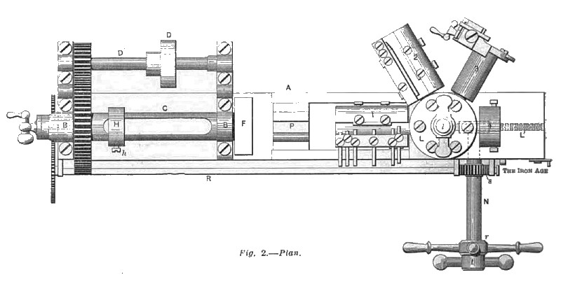 1901 Coulter & McKenzie, The First Large Turret Lathe (Plan View)
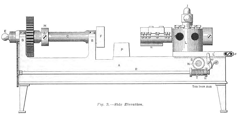 1901 Coulter & McKenzie, The First Large Turret Lathe (Side Elevation)
|
|