|
Title: |
1857 Article-Sparke & Co.-Sawing Machine |
|
Source: |
The Engineer, V4, 20 Nov 1857, pg. 378 |
|
Insert Date: |
7/4/2018 3:30:29 PM |
The first part of this invention relates to that part of sawing machinery which is employed to give motion to the timber under operation, for the purpose of bringing it up to and keeping it in contact with the saw during the cutting and of withdrawing it from the saw when the cut is completed. The second part, relates to the mode of driving reciprocating saws, or saws which act upon the material to the cut by successive strokes, and consists in the employment of a crank arm, the length of which may be varied when it is desired to change the length of the saw's stroke, such crank arm carrying at its extremity a pin which works in a transverse slot in the frame of the saw, and which, as the crank arm rotates, imparts the necessary reciprocating motion to the saw. Instead of a crank arm and pin, a disc and adjustable pin or other equivalent contrivance may be employed.
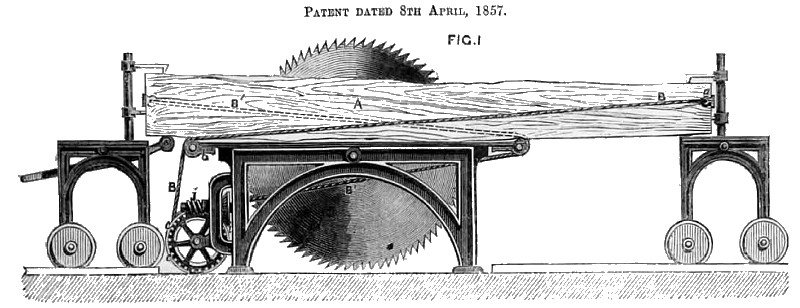
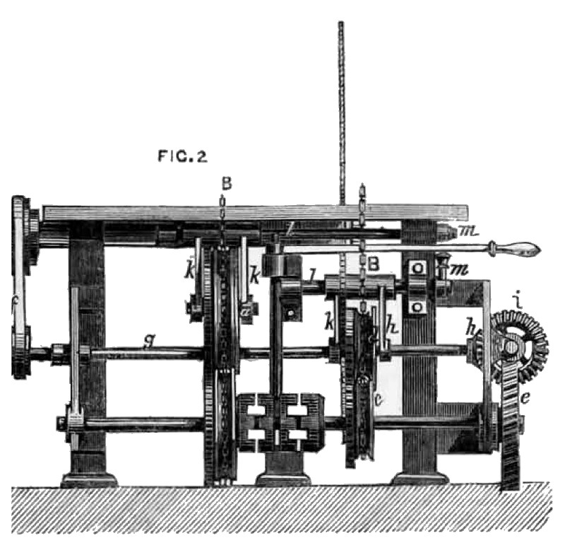
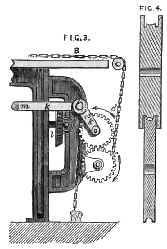
The illustrations have reference to the first part of the invention. Fig. 1 being a side view, and Fig. 2 an end elevation, partly in section, of a circular sawing machine fitted with the improved apparatus for bringing the timber to be cut up to the saw, keeping it in contact with it and withdrawing it from the saw when the cut is completed. The machine is formed with a frame, parts of which run on rails, and the tree A to be out is attached thereto by dogs. This frame, together with the circular saw, is formed and fitted as usual, or in any other suitable manner. In this machine two ropes B, B' (the latter shown partly in dotted lines) are employed, the former for imparting a forward motion to the timber A, and the letter for giving it a backward motion. The rope B is attached at one end by a claw a to the timber A, and is thence led over the roller b down and then over a second pulley d, and then falls slack to the ground. The lower pulley c is mounted upon an axle, driven by a worm wheel c, to which motion is transmitted from the saw spindle through a belt f, a spindle g, a bevel pinion hh, a bevel wheel i, and a worm j. These parts are shown separately in Fig. 3. The upper pinion d is mounted upon the axle, carried by the levers k, k, which are ?xed on a rocking shaft l. By raising or depressing the lever m which is fixed on this shaft l, the amount of friction exerted upon the rope B between the pulleys c and d may he increased or diminished in such a manner as to regulate the speed with which the timber is moved, either by allowing the pulleys c and d to slip more or less within the rope B, or by nipping them tightly against it. A cog wheel is mounted upon the axle of each of the pulleys c, d, so as to gear into each other, in order that the pulleys c, d, may he made to move with the same surface speed. The rope B', by which the timber is run back from the saw, may be acted upon by an arrangement of apparatus similar in construction and in action to that just described, the pulleys being made larger in this case to give it a greater speed if desired. A section of the pulleys c and d is shown in Fig. 4.
Courtesy of Grace's Guide.
GB Patent: GB-185,700,987
http://datamp.org/patents/displayPatent.php?number=185700987&typeCode=0&country=GB |
|
 1857 Sparke & Co.-Sawing Machine
 1857 Sparke & Co.-Sawing Machine (End View)
 1857 Sparke & Co.-Sawing Machine (Gearing)
|
|