|
Title: |
1880 Article-John McDowall & Sons., Muir's Planing Machine |
|
Source: |
Woodworking Machinery, Its Rise, Progress and Construction, 1880, pg. 80-87 |
|
Insert Date: |
7/10/2018 4:45:40 PM |
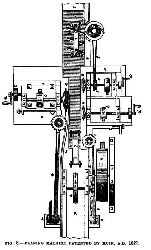
Fig. 8 represents a plan of the machine, slightly modified, to render the construction more easily understood by the reader. The machinery is adapted for the simple planing of boards, as well as the preparation of square-jointed or plain-jointed flooring. We shall commence our description by an account of those parts which constitute a simple planing machine, and then proceed to describe the apparatus by which it is adapted to the preparation of jointed flooring. The planing machine consists of a perfectly flat and straight bench ddd, which should be at least twice as long as any board intended to be prepared upon it. This bench is made fast to a block of stone c c or other solid matter, which, together with a suitable framing, serves to keep the machinery as firm and steady as possible. Along one side of this bench is a raised guide e e, which extends as far as the circular saws i, i; but only a part of it is shown in the figure, in order to bring some other arrangements more into view. About the middle of the bench a metallic plate a, a is let in flush with its surface, which forms a durable stock for the plane irons; these plane irons are of the usual form, but of greater breadth than the boards to be planed. The projection of their cutting edge is effected and regulated by screws, and the number of plane irons employed at a time is determined by the degree of finish required for the surface of the boards; three plane irons are, however, generally used, as shown at h, h, h, the dark spaces being the mouths of the planes; from this it will be seen that it is the lower side of the board that is planed, and the shavings are delivered under the machine. An endless pitched chain, having catch hooks at convenient distances, takes hold of the boards as they are put into the machine in succession, and drags them along the bench; the edge of one of the sides of each board passing under a rebate in the guide or fence (as shown in the figure) prevents the board from bending upwards by the action of the chain, while it is pressed down to the plane irons by springs or weighted levers, as seen at b, b, which are mounted upon antifriction rollers, the axles of which are so inclined as to cause the boards to be uniformly driven against the fence and to pass in a straight line through the machine. Motion is given by a band from a large revolving dram, placed above the machine (not shown in the figure), which communicates with the drum w, upon the shaft of which is a pinion that drives the toothed wheel j; the axis of the latter carries the pitched rigger t, round which the endless chain is passed, and stretched in a parallel direction with the bench, by passing over the pulley z, at the opposite end of the machine; at this place only a small piece of the chain is brought into view, as the introduction of the whole of it would hide or tend to confuse some of the other parts of the apparatus. The pulley z is mounted upon a tightening frame y which moves upon a joint at the lower end, the tension being increased or lessened by the wedges 1, 1, or by regulating screws. The parts we have thus described constitute a separate machine for the planing only of boards. For the preparation of plain or square-jointed flooring boards, the following additional apparatus is brought into operation. A part of the fence e is slightly hollowed from the direct line of the bench, to admit of projecting inequalities in the edges of the boards; these are removed by irons or cutters fixed on a horizontal revolving plate f, the periphery of which enters an aperture in the fence e; and it is on the edge of the board presented to this side of the machine that a tongue or feather is formed when required. To produce this effect two circular saws, g and h, are used, one of which, g, revolves under the board, and cuts it upward; the other, h, revolves above the board, and cuts it downwards, to such a depth only on each side as to leave a tongue or feather of the required thickness uncut. By the progressive motion of the board it next passes under the operation of two circular saws i, one only of which can be seen, as the other is directly underneath on the same spindle, and separated only by a ring or washer, which is of the same thickness as the tongue. These saws, acting horizontally, or at right angles to those at g and h, cut off the superfluous wood, and leave the tongue projecting from the board completely formed. The opposite edge of the board is cut parallel to the other by a circular saw k revolving vertically, which is called the "breadthing" saw; a guide fixed to the head of 0, which supports the spindle of this saw (but which cannot be seen in the figure), is so placed as to conduct the superfluous pieces, separated from the boards by the saw Tc, underneath the circular saw I; the slips are thus removed out of the way of the latter saw and preserved. The saw l revolves horizontally and is called the "grooving saw;" it is considerably thicker than ordinary circular saws and has long teeth to admit of their receiving a " set" to cut out the whole of the required groove at one operation. The spindle head which carries the grooving saw is adjusted and fixed by screws to a bracket attached to the head o, the latter being placed in slides, which keep it steady, and conduct it in a parallel direction when moved to or from the bench. All the parts that operate on this edge of the board being thus connected, advance or recede together. This movement is affected by means of a screw fitted with collars to the fixed puppet 3, and working in a nut in the back part of the head o; the screw is turned by the handle n, and an index on the head o points out the relative position of the circular saw k with respect to the other side of the machine, and consequently indicates the various breadths of the finished boards by pointing to a divided scale of inches and parts fixed upon the block c. All the saws are fixed on to the spindles in the ordinary way, by screws, nuts, and washers; but the spindles are considerably thicker than usual, to admit of their being fitted with cutters or irons, which, by cutting horizontally, rebate the superfluous thickness of the board to a sufficient extent from that part which is destined to form the underside of the floor in all flooring boards. The heads, which carry the vertical saws g, h, are placed on slides fixed to the block ccc, their horizontal position being adjusted by regulating screws, worked by the handles p and r, and their spindles elevated or depressed by proper adjusting screws. Motion is communicated by endless bands from a large drum wheel above the machine, such bands embracing all the vertical saw pulleys, and also the rigger or pulley w of the intermediate shaft v w; and this intermediate shaft, by means of half crossed or twisted bands 4, 4, gives motion to the horizontal saws i and I. The circular plate or plane / is also impelled by another half-twisted band 5, from a pulley 6, on the axis of the saw g. The power which impels the whole machine is derived from a steam engine or other prime mover applied to the shaft of the large drum wheel before mentioned.
A number of these machines were made and erected by Mr. Muir in Glasgow and other towns and were in operation for many years. Mr. John McDowall, of Johnstone, near Glasgow, made a number of machines on Muir's model, and afterwards introduced several modifications and improvements of his own, for which he obtained a patent in the year 1836. The chief of these improvements consisted in the introduction—in the place of the endless-chain feed, which, when planing thin stuff, had a tendency to tear the wood—of two pairs of rollers at the front and back of the machine, to feed the boards through the cutters, by means of frictional pressure. The rollers were turned and made to act like the rollers of a calendering machine; the upper ones were held down by weighted levers, which gave them an increased grip on the wood which passed between them. The rollers were found to answer their purpose well, and the thinnest boards were carried through the machine without difficulty. Another improvement was the introduction of a new method of cutting tongues and grooves on the edges of the boards. Muir employed four saws for this purpose, one cutting up> another cutting down, and two cutting in, so that two strips are cut off the sides, leaving the tongue or feather in the centre; this plan did not act well when working on thin wood. Mr. McDowall substituted a set of rotary cutters fixed on vertical spindles; these cutters were made the exact size of the tongue or groove required, and being placed on either side of the machine in brackets working on a slide, could be adjusted by means of a screw and hand wheel to suit varying widths of boards; this plan is in use at the present time. Mr. McDowall also, a few years later, introduced several other modifications in these machines, including a silent feed motion with differential action, and an arrangement of combined roughing and finishing cutters for thicknessing. The feeding motion was a decided novelty. As the deal entered the machine to be cut it passed beneath a set of feed cams, which nipped the wood and carried it continuously forward. This feed arrangement consisted of horizontal traversing plates of metal, tongued at opposite ends, to slide freely in corresponding grooves in the top plates of the standards, and upon these plates a pair of vertical parallel standards were attached; these standards were connected at their upper ends by a light cross-bar. Each standard was slotted down its centre, to receive and guide the traversing nut-bearings of the cross cam-spindle. A screw was passed down from above and through the nut-bearings, so as to allow the cam spindles to be set up or down. Each cam spindle had an eccentric cam loosely hung on it by an eye, the cam eye being fixed against an adjustable collar. Thus arranged, this nipper feed formed a complete traversing frame capable of free horizontal movement.
The primary movement was given to these nipping feeders—of which there were six altogether, three at each end of the machine—by a toothed pinion on the first motion shaft. This pinion geared into a large toothed wheel set on a cross shaft and carrying a second pinion in gear with a second spur wheel, fast on the actuating cam-shaft. On this shaft three separate cams or differential eccentric pieces were keyed. Over the periphery of each cam was set an anti-friction pulley, carried on the horizontal arm of a bell-crank lever, the three bell cranks being carried loosely on a stud shaft. The long vertical arms of these bell cranks were connected by eyes at their lower ends to their respective rods, which were severally linked by end and intermediate eyes to the bottom of each of the nipping frames. The three cams were so set at starting that they each acted at different periods of the revolution of their shaft in such a manner that an uniform feed motion was given to the board passing through the machine. This method of feeding the timber, although ingenious, had several objections, and has long been disused, but it certainly deserves a passing notice. |
|
 1880 John McDowall & Sons., Muir's Planing Machine
|
|