|
Title: |
1867 Article-Edwards, Stevens & Co., -Baldwin's Lathe for Turning Ornamental Work |
|
Source: |
Scientific American, V16, #17, 27 Apr 1867, pg. 268 |
|
Insert Date: |
9/29/2018 1:32:55 PM |
Improved Automatic Lathe.
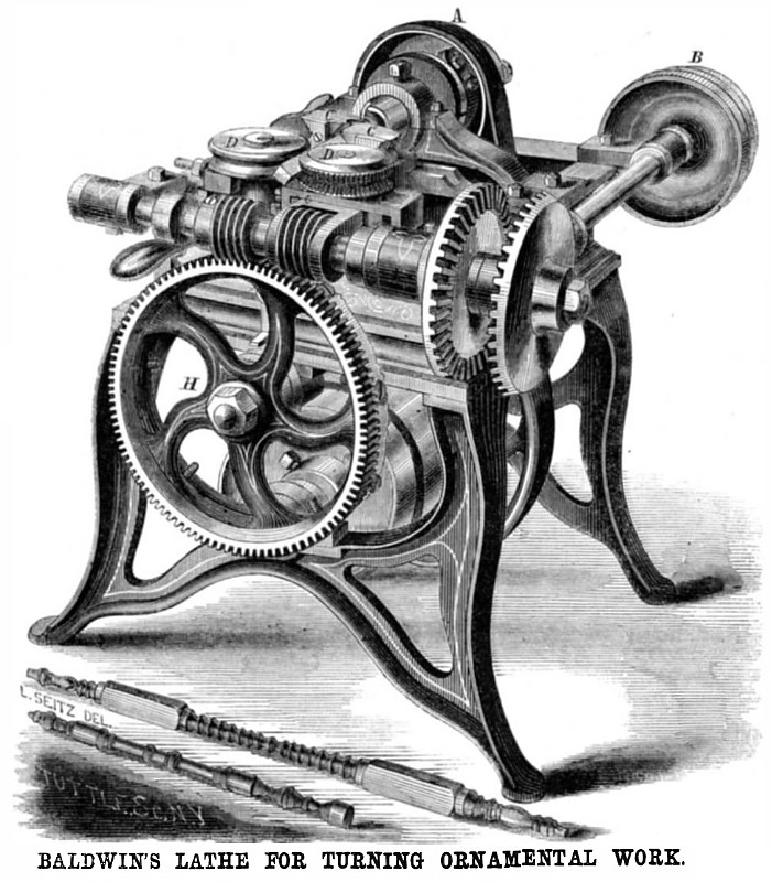
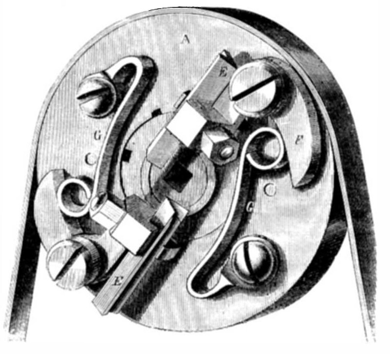
The engravings herewith given represent a very ingenious machine for turning beaded and plain wood work, for handles, chairs, settees, spokes, stair railings, and many other purposes. It is compact, direct acting, and certain in its operation. It will cut or plane in a square, octagonal, or any polygonal form, and turn plain or beaded at the same operation. Fig. 1 is a perspective view of the complete machine, and Fig. 2 the working side of the head for turning the round work.
The machine is driven by the lower shaft, which, by means of belts, gives motion to the cutter head, A, and the cone pulley, B. It also, by suitable connections, revolves the cutter heads, C. The head, A, turns loosely on a hollow arbor which is fitted with dies of different form to guide the work. In Fig. 1, the die shown is square to accommodate the square piece seen passing between the feed rollers, D, in Fig. 1. One of these rollers is toothed and the other plain. They are adjusted by springs to open or close together to admit the work to be turned, and they feed it to the heads, C, which also can be similarly adjusted. From these cutters the wood passes through the hollow stationary arbor and is turned by the cutters on the head, A. These cutters are V-shaped as seen in Fig. 2 at E. The cutters are secured by hook bolts to bell cranks, F, pivoted at the junction of the angles, and held pressed in toward the center of the wheel by springs, G. The outward movement of the cutters is assured by dogs attached to the crank levers, F, by means of slots through the pulley. These dogs connect with a lateral sliding bar, not shown, the end of which engages with the pattern plate secured to the large worm gear, H, seen in front of the
machine, Fig. 1. This pattern is of sheet steel or iron, the edge formed to present a section of the work to be done, and one can be changed for another at will. The wheel carrying this pattern is driven by one of the worms on the front horizontal shaft, the other driving the feed wheels, D. This shaft is driven by the cone, B, with the aid of bevel gears, as seen, which may be thrown in or out of gear, as desired, to actuate or stop the feed rollers or the pattern wheel. This is done by a lever operating a clutch in the usual manner.
A stick may be introduced into the machine between the feed rollers, D, and pass to the cutters, C, which may be of and shape to give the form required; thence through the die in the hollow arbor until the cutters on the head, A, engage with it and turn it to any form desired, their motion to or from the center being controlled by the action of the pattern on the rod, which opens them, and the pressure of the springs, G, which close them.
This machine is the subject of a patent issued Aug. 24, 1858. A patent is also pending through this office on other improvements. For further information address Frederick Baldwin, Brattleboro, Vt.
US Patent: 65,864
http://datamp.org/patents/displayPatent.php?number=65864&typeCode=0 |
|
 1867 Edwards, Stevens & Co., -Baldwin's Lathe for Turning Ornamental Work
 1867 Edwards, Stevens & Co., -Baldwin's Lathe for Turning Ornamental Work (Cutter Head)
|
|