|
Title: |
1889 Article-Valley Iron Works, The Valley Automatic Steam Engine |
|
Source: |
American Engineer, V18, 24 Jul 1889, pg. 28 |
|
Insert Date: |
10/12/2018 10:00:40 PM |
AUTOMATIC ENGINE
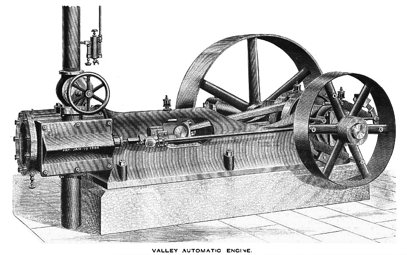
The style of engine represented in the accompanying engraving (which is an elevation of the valve side in perspective) was designed to meet the requirements of limited space when it is desired to drive from one wheel to line shaft. The engraving shows the style of two sizes, namely; 12x14 and 14x16, centre-crank engine.
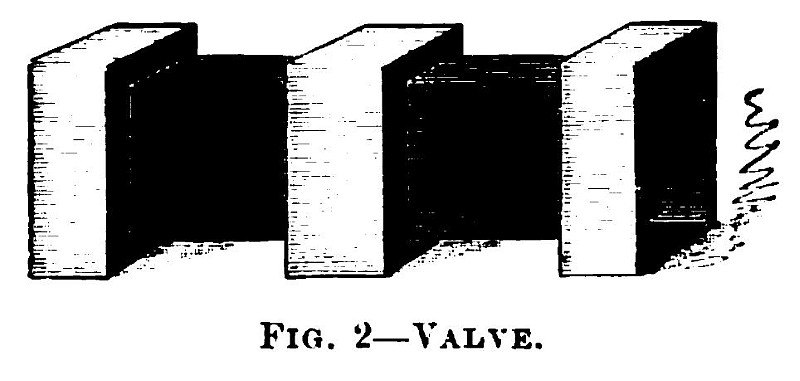
The two features that claim special attention are the slide valve and governor. These are represented by Figs. 2 and 3. Reference being made to Fig. 2 and the side elevation, it will be seen that the shape of the valve is square and is set in the valve seat with cover pointing to centre, or, in other words, it is placed diagonally. Over the valve is placed a cover. Between this cover and the seat are placed two strips of copper 1-1000 of an inch in thickness. They are for the purpose of removal and taking up the wear as the valve requires it. The objection of wear still existing in the piston valve, is entirely obviated by this construction. Live steam is admitted inside the cover around the valve, and exhaust steam is let out at the end. This construction enables the engine to be run under full boiler pressure with the exhaust chest cover removed, and a thorough inspection of the valve for leakage made under steam pressure. The exhaust, starting as it does at once into the steam pipe, obviates the objection of exhaust jacketed valves and cylinders. By the particular shape of this valve, the ports can be made large and, with its ample travel, admits, as the indicator cards show, of a most perfect diagram under high rotary and piston speed, giving a most perfect steam and exhaust line and a high initial pressure, resulting in a low terminal compared to average pressure.
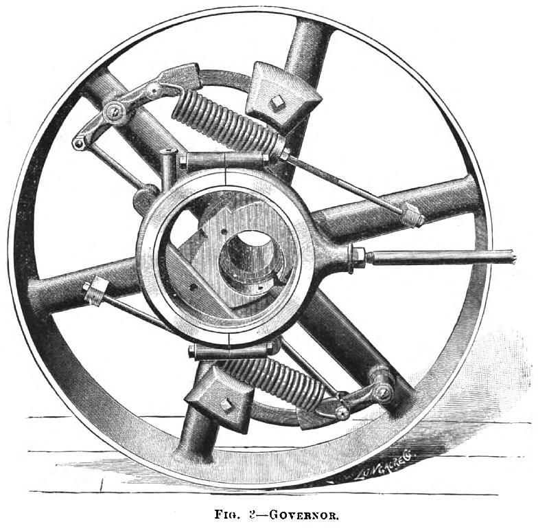
Reference being made to Fig. 3, it will be seen that the governor of this engine belongs to that class in which the operation is to move the eccentric across the shaft, altering its throw and varying the length of travel of the valve. In this manner it changes the point of cut-off to suit the varying conditions of load and steam pressure. The range of the governor is the earliest point of cut off or that which will restrain the engine under its lightest load and highest boiler pressure—while the latest point of cut-off allows full boiler pressure to follow for 7-10 of the stroke. This whole range of adjustment is under complete control of the governor within less than .02 variation of speed. By the train of mechanism employed the governor preserves a constant lead, which is of the greatest importance to insure good results. Owing to the perfect balance of the valve it has not been found necessary to design a governor that is locked in all positions, but, on the contrary, lighter springs and weights are used by this governor than any other of its class in the market, the valve movement not requiring that great amount of power in the governor that is given by heavy springs and weights. Dash pots and friction brakes are not required to insure steadiness. There are two sets of levers pivoted near the rim. The outward movement of these levers is produced by the centrifugal force of the weights and resisted by the centripetal force of the springs, the tension of which is controlled by the screws shown. The movement of the eccentric is in a straight line across the shaft and is slotted in a stationary sleeve next to the wheel. This movement of the eccentric is taken from the levers through the links shown. By this arrangement such an adjustment of centrifugal force of the weights and centripetal force of the springs can be employed that will admit of the best attainable results in regulation. The tension of the springs should be as much as the governor will admit of, and as near the theoretic tension as possible. Too much tension will be indicated by violent oscillation of the governor. Two-thirds of the distance from the center of the lever stud, or where the lever is pivoted to the center of spring stud or where the spring is hooked, is about the proper tension. Change of speed is obtained by shifting the weights in and out of the lever, or by increasing or diminishing them. An examination will show they are made with pockets to increase or diminish, and one weight is heavier than the other. This is done to balance the heavy side of the eccentric, and the heaviest weight should always be placed opposite the throw of the eccentric, or on the shortest lever. The governor ts entirely fitted with automatic lubrication, thus permitting of continuous running. Among other features in the details of this engine we notice the following: The piston is of the solid locomotive type, with rings entirely of spring packing. Its length is ample to insure large bearing surface, preventing wear and tendency to lower the rod. The rings being of spring packing also insure the cylinder, being one diameter all through. The cross-head is of cast iron with a steel pin cast in. By the method of casting employed it is burnt to the iron, and the first one to come loose has yet to present itself. The pin is flattened top and bottom and boxes milled to suit, preventing the connection from irregular wear. The shoes or sides are of cast iron, babbitted, and circular in shape, allowing of adjustment to the unequal wear of bearings and keeping the connection rod always in line. The cranks are large and heavily balanced. The pin is one-fourth the diameter of the cylinder, and the pin and shafts are ground to a perfect circle in special grinding lathes. The connecting rod is of forged wrought iron with solid end (marine style). The boxes are made of brass filled with babbitt and the babbitt is spun to size against the brass with the boxes revolving under a high speed, and the babbitt is forced out with small rollers under a heavy pressure This engine is known as the Valley Automatic Cut-off Engine; constructed at the Valley Iron Works, Williamsport, Pa. The Allen Manufacturing Company, of No. 55 S. Canal Street, Chicago, has the general sales agency. Engines of this class and make and of various sizes can be seen at the company's ware-rooms, where further information can be obtained. |
|
 1889 Valley Iron Works, The Valley Automatic Steam Engine
 1889 Valley Iron Works, The Valley Automatic Steam Engine (Valve)
 1889 Valley Iron Works, The Valley Automatic Steam Engine (Governor)
|
|