|
Title: |
1913 Article-Clipper Belt Lacing Co.- Factory View |
|
Source: |
Machinery Magazine, V20, Nov 1913, pg. 194 |
|
Insert Date: |
11/1/2018 1:07:15 PM |
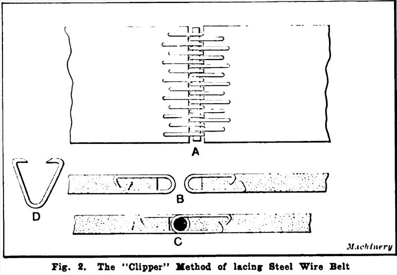
The steel wire belt lacing and method of application developed by the Clipper Belt Lacer Co., Grand Rapids, Mich., consists of wire clips which are clinched in each end of the belt to be joined, forming loops at the outer ends and locked together by means of either a rawhide or bamboo pin. This method of lacing makes possible the disjoining of the belt without destroying the lace or in any way affecting the joining members, it simply being necessary to pull out the rawhide pin. Fig. 2 shows two ends of a belt joined in this manner at A; at B the pin has been removed, disjoining the belt; at C a section of the belt is shown with a rawhide pin in place; and at D is shown the shape of the hook before being clinched in the belt.
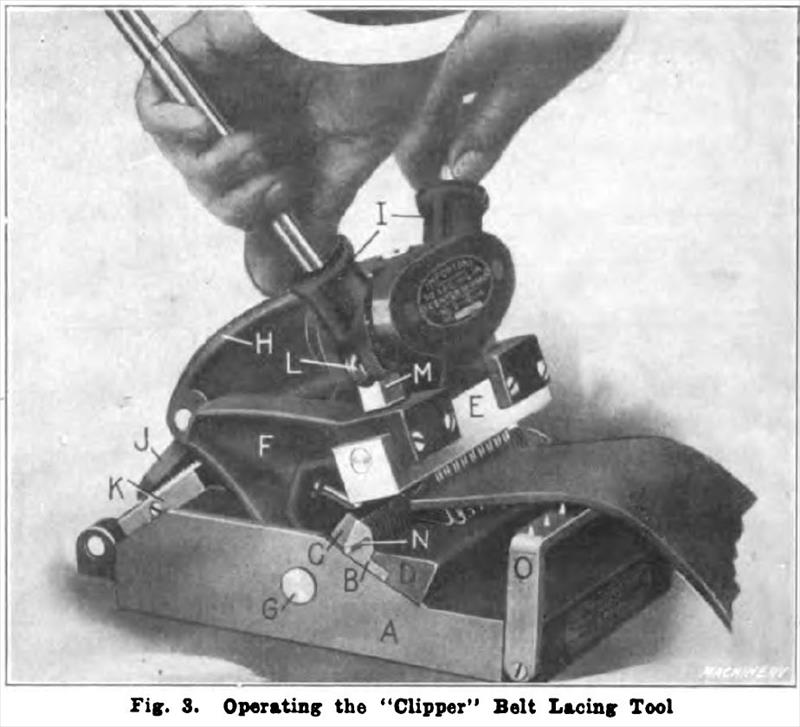
Construction and Operation of "Clipper" Belt Lacer The "Clipper" belt lacing tool shown in Fig. 3 consists principally of a frame or base A, carrying a comb B and lacer C for holding and closing the steel wire hooks, respectively, and an anvil D, on which the hooks are closed by means of the clinching bar E. Bar E, in turn, is held in a swinging arm or bracket fulcrumed on the king pin O. Center head H, carrying the operating lever sockets /, is also fulcrumed on this pin and is held in the desired position when inserting the hooks by means of a dog J, hinged to it and located by a ratchet K. Power to insert and clinch the hooks in the belt is secured by means of operating levers inserted in sockets 7, the levers being eccentrically fulcrumed and carrying the rollers L, which bear on the tracks M and operate the clinching bar.
In operation, the head is first thrown back by removing the dog from the ratchet; then the card of hooks is cut to suit the width of the belt being laced. This is accomplished with a pair of scissors supplied with the lacing tool, by cutting first one edge of the card and then the other, and then bending the card slightly back and cutting through the center. The card of hooks is now inserted in the lacer where it is held in place by the pin N. The center head is next brought forward and the dog and ratchet put in place, after which the belt, which has been previously cut square on the end, is placed between the hooks in the tool and on top of the belt holder 0, care being taken to keep the end of the belt tight against the lacer. Next the levers are inserted in the socket and pressed down, forcing the hooks into the belt. As the head is forced down it is drawn slightly forward each time the levers are raised, and this operation is repeated until the hooks are flush with the surface of the belt.
For lacing a belt wider than the capacity of the lacing tool, the hooks are inserted in sections. On a belt of such a width as to require two lacings, one section is put in at one end, clinched, and brought flush with the belt, and another section of lacing is put in at the other end, thus completing the lacing of one end of the belt; the other end is handled in a similar manner. For a belt requiring three lacings, the hooks are first inserted in the center portion of the belt, after which the hooks are put in on both sides of the center portion. It is always advisable to locate the hooks as near as possible, as this obviates any unnecessary strain on one side of the tool, insuring a much more even pressure. |
|
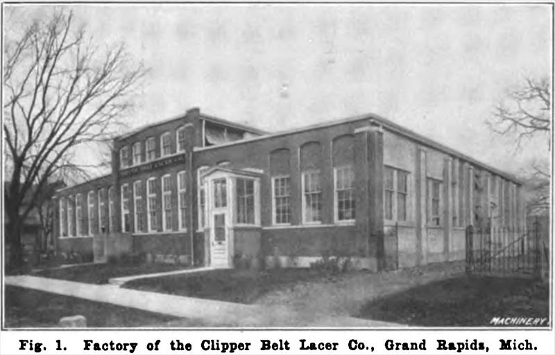 1913 Clipper Belt Lacing Co.- Factory View
 1913 Clipper Belt Lacing Co., Clipper Steel Wire Lacing
 1913 Clipper Belt Lacing Co.-Clipper Belt Lacing Tool
|
|