|
Title: |
1885 Article-Transmitting Dynamometer Co., Ruddick's Transmitting Dynamometer |
|
Source: |
Electric Illumination, V2, 1885, pg. 233 |
|
Insert Date: |
11/6/2018 1:45:44 PM |
|
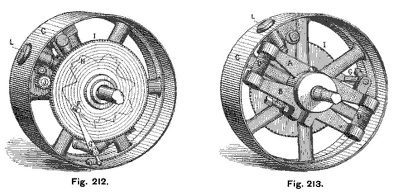
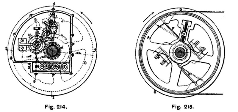
Ruddick’s dynamometer is one of those which are fixed directly on the shaft, taking the place of the pulley that would otherwise be employed to transmit the power. It consists of a pulley C (Figs. 212 and 213), a disc capable of turning about its boss, and of two arms A and B, fixed, the one to the dynamometer pulley and the other to the shaft H, and connected to the springs D, which are deflected proportionally to the power transmitted. The extremity of the arm B, which is the one keyed to the shaft, is connected at G to an index, coupled by a drag link to the dynamometer pulley. The opposite extremity of the index carries a pencil, which approaches more nearly to the centre of the disc H, as the power exerted is greater. This disc has a motion of rotation imparted to it relatively to the rest of the apparatus, by ratchet mechanism, put in operation by a button L, which is forced inwards by the shaft at each revolution of the pulley. The circles traced on the disc are each marked with two numbers, one indicating the turning force, and the other the corresponding horse-power. Valet—In the dynamometer, illustrated in Figs. 214 to 217, which is the invention of M. Valet, the disc D, keyed upon the shaft E, drives, by means of the springs F and snugs a, the pulley A, the work of which is to be measured. The flexure of the springs is transmitted by I iJ K, to the roller L of a totaliser, whose disc N, held against the roller by the spring j, gears with the wheel cl, mounted loosely upon the shaft, and held from rotating by the support G. The roller L is connected to the spindle of the counter S, and the whole of the recording apparatus is enclosed Within a box P to protect it from dust. The position of the axis I can be adjusted by a screw; the further it is from the centre the greater the motion imparted to the roller L by the flexure of the springs. |
|
 1885 Transmitting Dynamometer Co., Ruddick's Transmitting Dynamometer
 1885 Transmitting Dynamometer Co., Ruddick's Transmitting Dynamometer (Sectional Views)
|
|