|
Title: |
1882 Article-C. E. Lipe, Universal Milling Machine |
|
Source: |
American Machinist, V5, 10 Jun 1882, pg. 04 |
|
Insert Date: |
11/7/2018 11:44:07 AM |
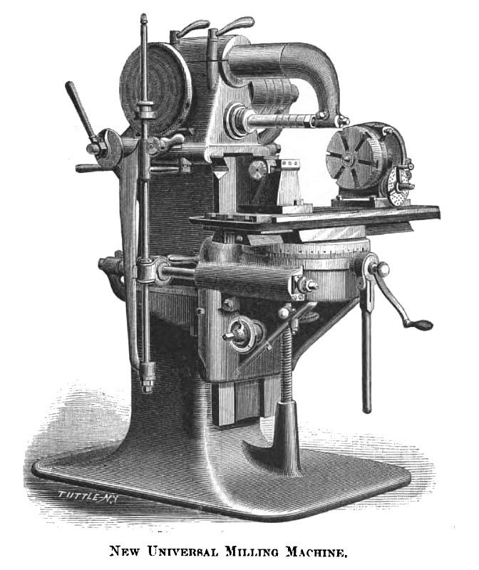
The universal milling machine herewith illustrated, and which was designed and is manufactured by C. E. Lipe, of Syracuse, N. Y., is the result of several years careful study and experiment; the aim of the designer having been to produce a machine capable of being readily and quickly adjusted to any of the many special operations that may be required of it, and in which all the moving parts may be set at any point within their limit of range without special preparation or change of parts; also to combine such mechanical movements as would allow of the greatest possible latitude between such limits without impairing its efficiency, and at the same time be capable of taking very heavy cuts when required.
The general arrangement of column and base, with the vertically moving knee and traveling work table, will be clearly under stood from the engraving. The column is cast hollow with shelves for tools and is provided with a door which is on the opposite side from that shown in cut. The transverse adjustment of the cutters to the work is effected by mounting the spindle and cutter arbor, cone shaft, outside center arm and the adjustable part of the feed mechanism, on a traveling head gibbed to slide on top of the column and connected by a rack and pinion movement, which is controlled and the head located by an adjustable lever and measuring dial. Distances are ordinarily read by a friction-clamped pointer, adjustable to zero, moving over the dial. A vernier arm reading to thousandths of an inch is also provided for very accurate adjustment.
The cone shaft is at right angles to the spindle, which is driven by a hardened steel worm and bronze gear enclosed in head, which is cast hollow with two bridges across from side to side. These bridges with the shell, support the solid boxes for spindle, and form oil compartments, holding a quart or more of oil each. They are filled from a pouch on the outside. The worm gear is thus made to revolve continually in oil, ensuring perfect lubrication; each bearing is also provided with means for self-oiling, in addition to the usual oil holes.
The spindle is threaded on front end, and has a hole 1 9/16 inches in diameter through it, tapering in front to receive the arbor. The spindle has tapered bearings, ground and fitted to boxes by scraping. The front bearing is 3 1/4 inches in diameter at the large end, and 6 inches long.
The outside center arm slides through a bearing in top of head and may be revolved up and out of the way, or taken out entirely, and when set in position can be quickly clamped with the grip levers closing the split joint. The knee is gibbed to the front of the column with a wedge-shaped gib.
Both the gibs to the knee and head are provided with tightening screws, to which are attached permanent wrenches, held with set screws. The knee is raised and lowered with a screw operated by a bevel gear and pinion, the pinion shaft projecting through the side of knee convenient of reach. A dial having two series of graduations, one reading by the decimal system to thousandths of an inch, and the other by 16ths, 32ds, etc., measures the movement.
The upper part of the knee is a circular box cast open on top. The box is covered with a circular cap on which are the dovetail guides through which the table slides. This cap is recessed into the box to keep it central and is fastened thereto by a novel application of an expanding ring, operated by a single stud which projects through the wall of the box. This ring has a > shaped groove on its periphery, which in expanding closes over similarly-beveled ledges on the inside of both cap and box. The edge of the cap is graduated for use in cutting spirals.
By this arrangement the table can be set to move at any angle with the spindles and quickly clamped, and as this ring is of large diameter (the outside diameter of box being 17") and bears evenly round the entire circle, the cap is held as rigidly as if it were solid with the knee.
In this box, securely protected from dirt and chips, is a large worm gear secured to a short vertical shaft, on the upper end of which is a pinion projecting through the cap and engaging with a rack recessed into the bottom of the table. This shaft also carries a bevel gear which meshes with a pinion on the end of the short shaft projecting through the front of the box for a hand crank, and also a hand lever with friction grip. The gearing is so arranged that one turn of this crank moves the table 2", thus providing for the rapid movement of the table along its path, to facilitate getting work in and out of place.
The automatic feed of the table is accomplished by means of a leather-covered friction disc, secured to the end of the cone shaft, which drives a vertical shaft carried by a bracket hinged to the head. A small pulley splined on this shaft, and held at any point by a spring-pressed catch, bears against the disc and may be set either above or below the center, to feed in either direction as may be desired. The pressure between the pulley and disc is regulated by an adjustable spring tension, and the feed can be set at any point without stopping the machine. This vertical shaft also carries a splined worm driving a worm gear splined on a horizontal shaft carried by the knee and a backward projecting bracket. The connection between these two shafts is thus made universal, the worm and gear being surrounded with a case which is free to slide on either shaft. A worm on the horizontal shaft engages with the larger gear in the knee completing the automatic feed. A clutch joint near the center of this shaft allows the worm to be dropped out of gear to stop the feed; also, to allow the rear portion of the shaft to be disengaged from the worm portion for the purpose of obtaining a powerful hand feed, by applying a crank to the front-projecting end.
The table has three bolt slots running lengthwise and is encircled with a pan set sloping towards one end. The front edge of this pan is raised flush with the surface of the table to make a support for overhanging work. The table can be fed its full length in either direction, and when placed so that one end will pass the column may be swung around parallel to the spindle and used as a boring mill for short holes; or, turning a complete half revolution, work may be done on both sides of a piece without resetting, thus ensuring perfect parallelism.
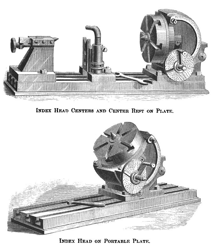
The index head, in design, is an entirely original conception. It is a hollow box, the outline of which is about two-thirds of a circle. The opening, in front or chord side, is surrounded by a heavy flange, and bored out as large as permissible. This forms the front-bearing of the spindle and face plate, which is cast in one piece. A rear and smaller bearing is provided on the circular part of the case. The end of the spindle projects through the case and is held from coming out by a recessed nut and washer. The spindle also carries an accurately-divided steel gear of sixty teeth. This gear is made as large as will go through the opening in front, or about 6" in diameter. Directly under this gear the box is pierced from the side. In this opening is inserted a long bush, through which a steel worm engages with the gear. An index plate secured to the outer end of bush, and an adjustable arm and index pin attached to the projecting end of the worm, completes the dividing mechanism. Substantial but delicate adjustments are provided for eliminating lost motion.
On the periphery of the case is turned a dovetail shoulder, which slides around in a corresponding groove in the quadrant-shaped base. The case is graduated on its edge and may be clamped at any angle of elevation from 15° below a horizontal line to a vertical position, being equally stable in all positions. The face plate is no farther from the bed in one position than in another, and being seated to the case, and adapted to hold work directly on its face, forms a stiff and substantial device for cutting bevel gears and other work requiring angular motion. The tail center is also of a strong and substantial design.
An adjustable center rest of novel design also accompanies the outfit, and an extra bed or table, with straps for securing it to the table of the machine, is also furnished. With the centers arranged on this bed the line of centers may be set at any angle with the sliding table. A sufficient number of index plates are furnished to divide all numbers to 100, all even numbers to 200, besides other numbers incidental to this system of indexing.
A complete automatic spiral cutting outfit is also furnished when desired, which will evolve spirals of any conceivable pitch greater than one turn in four inches, the limit of length being about 10". A heavy vise with steel faced jaws 7½" long by 1¾" deep opening to 4½", is also furnished.
The machine is driven by a 3" belt and has 4 changes of speed. It is powerfully back-geared in the worm and worm gear.
The weight of machine and attachments is about 2,800 pounds.
The countershaft, making 275 revolutions per minute, is driven with a 4½' belt, and being placed directly over the central position of cone shaft no trouble is experienced by the short movement of the cone and head. |
|
 1882 C. E. Lipe, Universal Milling Machine
 1882 C. E. Lipe, Universal Milling Machine Index Head
|
|