|
Title: |
1880 Article-Columbus W. Corr, Helve Hammer |
|
Source: |
American Machinist, V3, 06 Nov 1880, pg. 5 |
|
Insert Date: |
3/9/2019 1:30:23 PM |
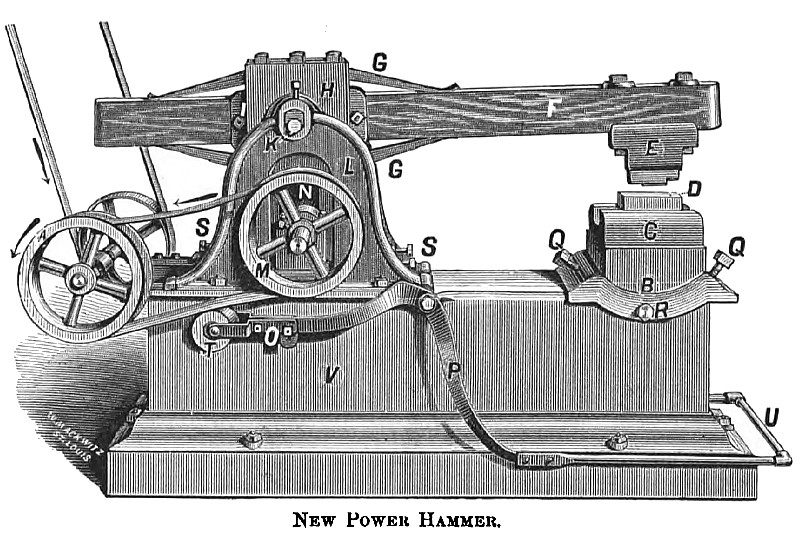
A New Power Hammer
The new power hammer, illustrated upon this page, is constructed so that the downward stroke is one-sixth quicker than the upward stroke. This feature is calculated to lessen the power required to perform the up stroke and increase the effectiveness of the down stroke.
The semi-elliptic springs, shown on top and bottom of the beam, serve to balance the stroke, so that the hammer may run from 350 to 450 strokes per minute, with safely to the machinery. The hammer is adapted to almost any form or kind of forging. Large dies maybe inserted for various forming and welding, such as making plow shares and other articles, which require that the operation be commenced with a light tap and increased to a heavy blow at the will of the operator. It is claimed that the hammer is always under perfect control of the operator, to start and stop, and to increase or diminish its power. With a slight pressure of the foot, the stroke may be increased from the lightest to the heaviest desired.
It is claimed that the hammer is free from any side motion, always striking unerringly in one place. Thus, shears and dies combined, may be used for cutting and forming small staples, and all work of this class which can be done with one stroke of either cold or hot iron.
The whole structure is mounted on A substantial iron bed V, 18 inches deep, 22 inches wide and 5½ feet long. Attached to this bed V, are two circular arms L; between them is pivoted near their top, at K, an oscillating frame H, having an opening longitudinal, in which is attached two semi elliptic springs GG. and two plates I, with trunnions projecting laterally through the oscillating frame at K; the hammer beam F, is inserted between the springs GG, and the trunnion plates I, which are bolted firmly to beam F at I; the ends of the trunnions and outsides of the oscillating frame H, rest evenly against the inside of the circular arms L; at K a shaft is passing through the trunnions and beam F, and made ridged in them with its ends resting in boxing at K. Caps are provided to cover the ends of the boxing and shaft with set screws projecting against the ends of the shaft, which secures it against end play.
By these mechanical arrangements the beam F and oscillator H are securely attached independently, vibrating on one common center, allowing no side play of the hammer E, admitting F to the free action of the springs GG; in the lower end of the oscillating frame at N is a lateral opening 10 inches vertical by 6 inches longitudinal and 4 inches laterally, with flanges projecting longitudinally one inch into this opening from both sides. This makes the opening two inches smaller on the outside than the internal cavity; the rear and front internal walls are provided with steel plates, 4x10 inches, ¼” thick, resting against the inner ends of four set screws not shown, provided to adjust these plates to or from the sliding box at N, to compensate for wear and prevent lost motion. These plates and flanges from the slides and guides between which a loose box and eccentric is provided with shaft projecting laterally through boxing at N, which project upwards from an adjustable frame immediately under the oscillator H; this permanently locates the eccentric and shaft in the lateral opening in the oscillator H, at N. The adjustable frame mentioned rests on suitable bearings on the inside of the circular arms, L, and is fastened down by four bolts passing through suitable slots in the adjustable frame, entering the bearings on the arms L. This frame is adjusted back or forth by set screws SS; this adjustment is for the purpose of giving a greater or les distance between the anvil and hammer at D, as may be desired for large or small work, long or short dies, etc.
The anvil B, weighing 500 lbs., sits down in the bed at R. and rests on circular bearings (between R and B), which radiate to the center of the top of the anvil at D, and is held rigidly in any position longitudinally desired by set screws QQ, with their inner ends resting on shoulders on the sides of the anvil B, which projects down about ten inches; between this lower projection and the internal wall of the bed is sufficient space to admit of any adjustment desired. This lateral adjustment is accomplished by set screws R, passing through the sides of the bed V, with their inner ends resting against the anvil which holds it rigid at any lateral adjustment. By this arrangement the anvil is accommodated to all and any class of work or shape of dies.
The anvil is constructed in two parts. Four inches of the top C, may be taken off, leaving a suitable place to insert large dies for various purposes, such as dies for welding plow-shares and dies for forging journals on large shafts. A counter shaft, provided with suitable pulleys, is attached on the rear end of the bed; this shaft is kept constantly in speed and power by the vertical belt in the direction indicated by the dart ;the other end of the shaft is provided with a flanged pulley, corresponding to a flanged pulley M, on the eccentric shaft; around these pulleys is placed a loose belt in contact with this belt is a press pulley T, adjustably attached by two arms to the projecting end of the treadle P, at O If the foot be placed on the treadle at U, and | it be pressed down, the break on the opposite side breaks contact with the balance wheel (not shown); the press pulley will at the same time tighten the loose belt on the flanged pulleys. This gives motion to the pulley M, in the direction indicated by the dart. Its motion is increased by a heavier pressure until it rolls off the same surface of the other flanged pulley; this would be the full speed, which may be diminished to any speed desired by lessening the pressure on the loose belt. By this means motion and power is given to the eccentric, which carries back and forth the lower end of the oscillating frame H; this gives vertical motion to the springs GG, which imparts corresponding motion to the beam F. These springs accomplish a three-fold object:
First; They carry the hammer E up and down.
Second; They cushion the hammer at the returning points and give off that power which was stored in them while cushioning.
Third; By the power exerted in the machinery they follow up and impart still greater force to the blow.
It is found by this arrangement of eccentric loose box and oscillator that when the machinery is moved in the direction indicated that the downward stroke is one-sixth quicker than the up stroke; this is a natural result, for the down stroke is performed while the eccentric is revolving above the center of its shaft and nearest the fulcrum of the operator H. With the present arrangement the downward stroke is performed with five-twelfths of the revolution and the up stroke is performed with seven-twelfths; the difference is two-twelfths, which equals one-sixth. The up stroke is performed while the eccentric is revolving below the center of its shaft and in that part farthest from the fulcrum of the oscillator H, so if the machinery was reversed the quick stroke would be up and the slow stroke would be down.
This new power hammer is the invention of C. W. Corr, Carlinville, III.
US Patent: 206,665
http://datamp.org/patents/displayPatent.php?number=206665&typeCode=0 |
|
 1880 Columbus W. Corr, Helve Hammer
|
|