|
Title: |
1922 Article-Precision & Thread Grinder Mfg. Co., Precision & Thread Grinder |
|
Source: |
American Machine and Tool Record, V22, Dec 1922, pgs. 43-48 |
|
Insert Date: |
3/31/2019 9:11:21 PM |
THE PRECISION AND THREAD GRINDER
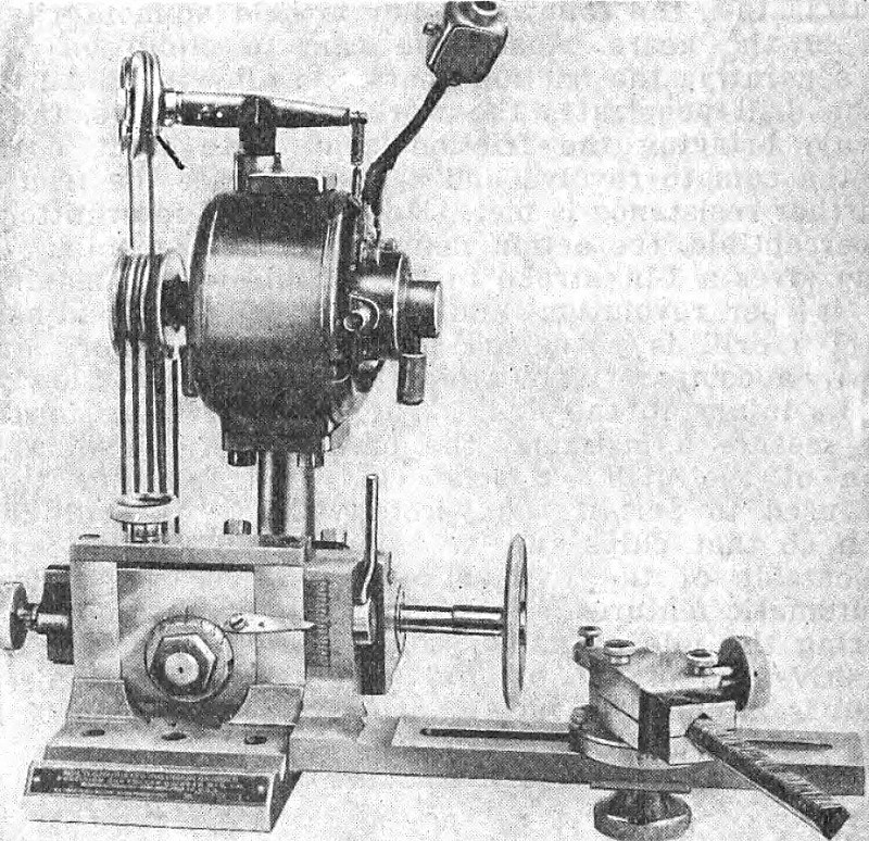
In modern machine shop practice the grinding machine has become an indispensable tool, because of the accuracy now demanded in the manufacturing and fitting together of various machine parts and gages. The rapid strides recently made toward accuracy and the perfection of details have developed a demand for more satisfactory machines and methods for producing finished hardened threaded surfaces which shall be accurately round and have all surfaces in concentric alignment together with a smooth and polished surface of the highest degree. To meet the demand for a tool that would accomplish such work on a commercial basis the Precision & Thread Grinder Mfg. Co., 1 South 21st street, Philadelphia, is offering the grinder illustrated herewith. The grinder is made in two models, Model "C" being for use in front of the lathe center, and Model "D" is for use in the rear of the lathe center. Fig. 1 illustrates the machine alone and is of' the Model "D", exceptionally and proportionately powerful and substantial in construction and is primarily designed for the manufacture of hardened and ground taps and hobs, and for internal and external thread gage grinding. In addition to this it is extremely efficient in grinding unusual operations frequently met with and such as do not come within the scope of the standard types of grinding machines now on the market; such as surfaces of peculiar angles, radii, both concave and convex, combinations of straight and tapered surfaces, straight and curved surfaces or a combination of the three—straight, tapered and curved, all in the same job and at the same setting. It may also be used as an attachment on any size or style of machine tool doing the grinding operations before the job is removed from the setting for machining. The perfectly balanced motor, pulleys, spindle and wheels eliminating all possibility of chatter or rough surfaces.
The multi-graduations provided, namely, vertical, longitudinal, angular, automatic vertical truing bar and the swivel graduations on the diamond holder dial provides the means for facilitating the quick and easy accomplishment of any or all of the operations referred to. It is to be noted that these five different traverses with graduations are an exceptional advantage since the value of the graduations lies in the fact that the wheel can be brought to pre-determined levels, sizes or spaced distance without the necessity of stopping the operation to measure the work and thereby enabling the operator to duplicate parts and fittings precisely, and in addition centralize bearings with the maximum of ease and rapidity. The Model "D" attachment is primarily designed for use in the rear of the lathe center and is mounted upon the back-tool rest. In the absence of back tool-rest it is mounted upon a special fixture of approximately the same height as the front tool rest, the grinder being on the other side of the job makes it very convenient to gauge the work. The Model "D" is equally adaptable for work on other machine tools as well as for bench grinding, being universal in scope irrespective of size of work it is engaged upon.
In setting up the grinder on a lathe it is first clamped on top Of the tool rest of the lathe, the angle inclination of grinding spindle is then set, down, for right hand threads, and up, for left hand threads, in accordance with chart, then by means of the vertical traverse, the center of the wheel is brought in alignment with the lathe centers and the traverse locked to eliminate possible vibration. The dressing arm bracket is attached with the vertical graduations on same in accord with the angular setting of the grinding spindle. This setting always brings the diamond point in alignment with the center of the wheel. In dressing the wheel, the truing cut must be started from the outside of the Wheel. On small lathes it is necessary to use an extra-long tailstock center furnished with the equipment. Should this prove undesirable, the grinder may be set at 5 degrees angle to lathe and the wheel dressed 5 deg. minus on one. side. and 5 deg. plus on the other side. On very small tool room lathes the compound rest should be set 180 deg., thereby providing ample room crosswise.
The grinding spindle is built on the same principle as the largest guns, the shaft being originally straight and the larger diameters, pulley and ball bearing cones being shrunk on. The spindle is mounted in five combination annular end thrust "Norma" precision ball bearings made adjustable for end thrust and radial wear, affording the maximum of efficiency and obviating heating and expansion either in diameter or length. Correctness of alignment is never out as the take-up adjustments on account of wear in this form of bearing do not incline the spindle out of original alignment, as is the case when solid bearings are used. Ample provision for lubrication makes it practically foolproof and it is also fully protected against oil leakage and the entrance of dust by means of steel felt-lined fittings at each end. The spindle alignment may be inclined to any angular position. Vertical traverse adjustment sufficient to bring the center of the wheel in alignment on any size lathe is also provided for. The spindle housing has a longitudinal traverse, facilitating quick adjustment of the wheel in relation to the work, in a great variety of classes in grinding. The multiple lead threads or worms are of especial advantage in that the wheel may be brought to and from sufficiently to precisely grind the other threads on the same screw or worm. The grinder attachment is composed of three units (1) base (2) spindle housing with motor and (3) wheel truing arm bracket. The base carries the vertical traverse plate in which the spindle housing fulcrums. To it is also attached, by a half turn of a breech lock screw the wheel truing bracket, this method of separation affording a distinct advantage in the versatility obtainable. On grinding operations where lack of space prevents the positioning of the base on the job or on the machine tool, the wheels can be trued to the shape required, units 1 and 3 can be removed and unit 2 can be clamped to the job or machine tool by simply passing the fulcrum post through a small angle plate made into such shape as will be found best adapted for the particular work in question. The range of operations that may be performed is practically unlimited since the machine will grind on any space, plane or body in which machining is done. The base unit I is provided with a "V" groove for quickly clamping the machine to a circular arbor or shaft. The spindle housing contains a longitudinal traverse, which is converted into a vertical by simply placing the spindle housing in a vertical position, the motor always retaining a correct alignment with the spindle pulley. In fact, the machine will operate under all conditions and in all positions.
The unit 3 can also be used on any machine tool using grinding wheels to true the wheels on the machine to any angle or other form required. The vertical graduations on the upper front of the bracket (unit 3) permitting of automatically setting the diamond in center with the previous setting, there is no adjustment lost by reason of the detachment of the bracket (unit 3) during the process of grinding.
Briefly stated, this grinder attachment may be used (1) complete in itself (2) as a grinding unit comprising only unit 2, and as a wheel truing device on other grinding machines by the use of units 1 and 3, only.
The spindle speeds vary, depending on the size of the grinding wheel used. Where a 6-in. wheel is used for external grinding, the spindle speed is approximately 7000 r.p.m. But where a wheel of less than I in. diameter is used such as for small internal grinding the driving pulley is put on a large motor pulley and on the small spindle pulley which permits of running the spindle around 20,000 r.p.m.
An exceptional and successful feature of the machine is the type of transmission used which permits of the spindle being run without any loss of power, or the creation of frictional heat, this being due to the fact that the belt may be run comparatively slack without slippage, owing to its triple contact with both driving and driven pulleys, any excess slack that might occur being automatically taken up by means of idlers located at the top of the motor having a spreading adjustment for increasing the distance as the belt may stretch.
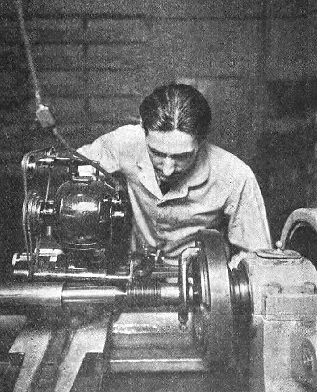
Separating arrows indicate the adjustment necessary for taking up the end thrust wear. A knurled knob is provided, operating the horizontal traverse to adjust the wheel in relation to the lead of the thread, and after the grinding operation has started, to adjust the wheel to grind on the side of the angle having the greatest amount of distortion, also when nearing the finished diameter size; to bring the wheel slightly to one side in order that machine will grind on one side of the angle only, thus making it possible to grind to within a 0.00005-in. limit. Fig. 2 is an illustration of "Grinding a large thread gage" and showing how the machine is "tipped" to obtain the proper helix angle.
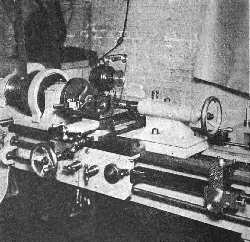
Fig. 3 illustrates the grinder and Precision thread lead variator installed on a lathe. The new thread lead variator and the Precision grinder being used in conjunction producing threads with precision leads on any lathe even though the lead screw may be worn. With this variator metric threads or threads of off or unusual leads can be cut on any lathe. The lead may also be elongated sufficiently to compensate for shrinkage in hardening. The variator is made in two sizes and is adjustable to fit all lathes. |
|
 1922 Precision & Thread Grinder Mfg. Co., Precision & Thread Grinder
 1922 Precision & Thread Grinder Mfg. Co., Precision & Thread Grinder
 1922 Precision & Thread Grinder Mfg. Co., Precision & Thread Grinder
|
|