|
Title: |
1863 Article-Merrill Bros., Hotchiss' Atmospheric Hammer |
|
Source: |
The Engineer, V15, 01 May 1863, pg. 247 |
|
Insert Date: |
4/9/2019 4:28:09 PM |
The object of this invention, by B. Hotchkiss, of New Haven, U.S., is chiefly to regulate the blow of the hammer, and give elasticity to the parts so as to give an elastic blow with the hammer, and at the game time prevent the breakage of the parts, which is one of the chief difficulties in the operation of trip and steam hammers. This hammer is provided with an air cylinder, in which a piston is permitted to move and act upon air contained in the piston in such a manner as to cushion the effect of the blow and give it a portion of elasticity. The piston rod in this machine extends down from the piston in the air cylinder and is connected below to the hammer.
The first part of the invention consists in the manner of connecting the upper framework with the anvil block by means of the superposition of elastic washers between the heads of the bolts which secure the parts together and the flanges through which the bolts pass, and also by the superposition of like washers between the nuts and washers at the ends of the bolts and the flanges through which the bolts pass.
The second part of the invention relates to the combination with the air cylinder and hammer of certain air passages through which external air may be received to modify the effect of the blow, and discharged to allow the piston inside of the cylinder to slide freely in certain parts of its stroke, the passages being operative without being opened or closed by any automatic mechanism except the piston.
The third part of the invention relates to supplying the cylinder with air, and discharging air therefrom by means of certain valves, which are operated by mechanism for the purpose to vary and modify the stroke so as to cushion the blow in the proper manner for the work to be performed. These valves are placed near the ends of the cylinder, though not entirely at the ends, and are worked by means of mechanism which is automatic in its operation, and which may be adjusted to suit the exigencies of the case. In general practice, perhaps, two adjustable inclined planes may be the better means for operating these valves, though other devices may be used.
The fourth part of the invention relates to the combination with the valves above mentioned of the air passage connecting from one valve to the other, so that the effect of the discharge of air through one valve shall be to force the same air into the other end of the cylinder. In the use of this device the same atmospheric air is made available for working the cylinder without the necessity of any additional supply from the outside.
The fifth part of the invention relates to the construction of the piston rod to obviate the well-known difficulty of breakage thereof near the hammer, and in connection therewith of the device, hereinafter described, by which the enlarged portion of the piston rod may be passed through the stuffing-box which leads to the air cylinder above mentioned.
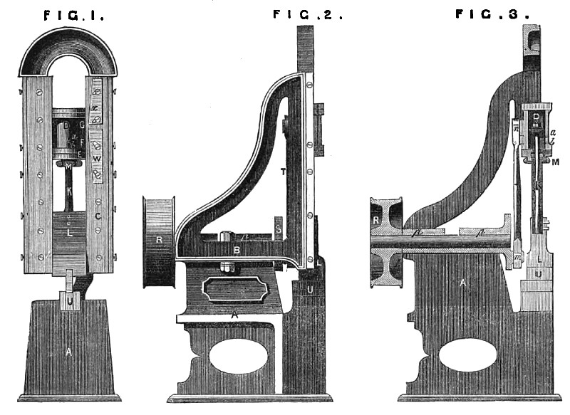
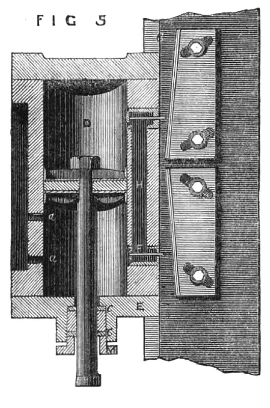
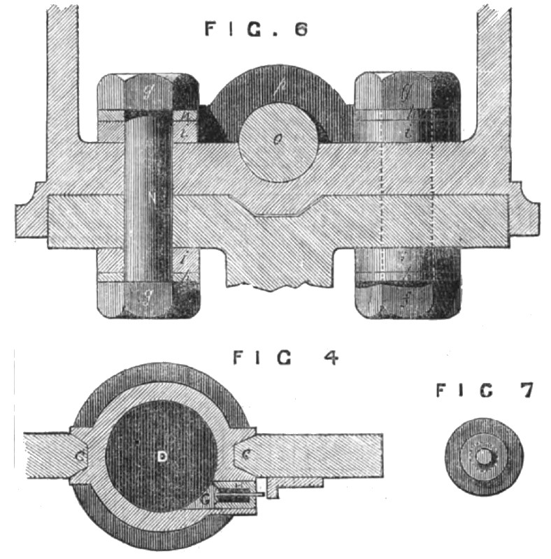
Fig. 1 is a front elevation of the improved atmospheric hammer; Fig. 2 is a side view thereof; Fig. 3 is a vertical central section showing the parts beyond the driving shaft; Fig. 4 is a horizontal section of the cylinder, and a portion of the ways or guides between which it slides, showing the construction of the valves for admitting air to and from the cylinder, and a device for working them; Fig. 5 is a detail sectional view, in elevation, showing the name feature of the invention, and also the independent air passages which may be used without valves, as will be more fully described below; Fig. 6 is a detail view, in vertical section, showing the mode of connecting the upper framework to the anvil block so as to 6ecure the parts firmly in position, and yet prevent the breaking of the parts by the concussion of the hammer; Fig. 7 is a detailed view illustrating the construction of the stuffing-box in a manner to allow the enlarged portion of the piston rod to be readily passed through from above, and the stuffing-box afterwards made available to make a close fitting joint around the piston rod.
A is the anvil block or frame upon which the parts are supported. The upper framework B is bolted to the lower or supporting frame A by means of bolts N, N, as shown in Fig. 6. These bolts are constructed in the ordinary manner with heads f, nuts g, and washers h, as usual. To give some little elasticity to this connection of the parts, elastic washers or rings i are placed between the heads of the bolts and the flanges, through which they pass to unite the parts, and elastic washers i are also placed between the washers h and the flange above, through which the bolt passes for the purpose above stated, and the nuts are screwed upon the bolts till the washers i are sufficiently compressed to hold the upper end and lower parts firmly together, but not so much but that they will yet yield slightly to the concussion produced by the fall of the hammer. The upper part or upper frame B is so constructed as to form guides C, C, to receive and guide the air spring cylinder D, which is constructed in some respects similar to a steam cylinder, with appropriate heads, and which receives motion from the main shaft by means of the connecting rod T. This cylinder D has two or more air passages a, b, in the side of the said cylinder, which passages open from the cylinder to the external air. H is an air passage which connects the openings which contain the valves G, g, and is intended to allow the air which may be forced out of the cylinder at one end to pass into the other end of the cylinder, so that no loss may be occasioned; and no outside communication is in this case necessary. I is a piston arranged within the cylinder D, and has its rod K extending through the lower head E of the cylinder, and attached to the hammer L. As in all hammers constructed and operated by a piston rod there is some liability to break the rod at its connection d with the hammer, this objection and difficulty were overcome by making a rod larger at the connection rf, and reducing from that point to the proper size of the piston rod. To do this a hole for the rod is made through the stuffing-box gland W, and also through the cylinder head E, of sufficient size to allow the enlarged portion d of piston rod to pass freely; and to pack the stuffing-box there are placed within it plates e, e, each divided as represented in Fig. 7, and the hole through these plates fitting the smaller part of the piston rod. The plates being in parts can be placed in the box after the enlarged part of the rod has passed through, and the packing may be placed between the upper and lower plates, and compressed in the ordinary manner. O is the driving shaft, which has its journals supported in boxes P, P. A pulley R is attached to this driving shaft, and at the opposite end of the shaft a crank wheel is fixed, in which a crank pin m is inserted, which crank pin extends through the connecting rod T, the upper end of which is by a similar pin n connected to the cylinder D. By applying power to the pulley R, motion will be imparted to the shaft O, and thence through the connecting rod T reciprocating vertical motion will be given to the pneumatic or air spring cylinder D, and in consequence thereof the hammer will be lifted and forced downwards towards the anvil U, or any article placed thereon. During each elevation or depression of the cylinder the piston will pass by the air passages a and b, and compress all the air that may in the cylinder between the air passage next the cylinder head which is approaching the piston and the said cylinder head. This compression of the air while the cylinder is descending will act as a spring to overcome gradually the inertia of the hammer, and prevent the piston from coming in contact with the lower head of the cylinder; so during the descent of the cylinder the air will be similarly compressed in its upper part, and will in like manner relieve the cylinder head above from the shock of the blow. The quantity of air compressed in the cylinder materially affects and controls the stroke of the hammer, and it will be obvious that by closing the lower hole or passaged, and opening the upper, a quantity of air is compressed below the piston equal to the contents of the cylinder below the upper opening a; but by leaving the opening b open the stroke is thereby reduced, as a less compression of air takes place, as it is obvious that the hammer will not be raised until the piston is met by the air below it in the cylinder, and that the cylinder produces no material effect upon the hammer between the points at which the air is left free to escape. This change, by means of a series of openings in any ordinary work not largely variable, may be sufficient for the purpose desired, but where a still greater range of variation in the stroke of the hammer is necessary, there are fixed in the side of the cylinder puppet valves F, G, as represented in Figs. 4 and 5. These valves open inward, and the operation of opening them is performed by the stems r, s, of the valves, which extend out through the cylinder, striking against the adjustable inclined planes W, X, which are fixed upon the guide C for that purpose. These valves may be usually kept closed by spiral springs, or otherwise as may be desirable. It will be obvious by an inspection of the parts that the inclined planes W, X, may be so adjusted as to open either valve at any portion of the stroke which is likely to be desired. By this the effect of the air cushion may be varied to any extent, according to the work upon which the hammer is to be used. By opening the lower valve before the cylinder has reached its extreme height the air compressed below the piston will pass through the passage H and upper valve into the space above the piston. The result is that the hammer begins its descent before the cylinder does, and while the crank is passing its upper dead centre, and the hammer will reach the anvil before the cylinder will have attained its lower extreme. But before that point is reached by the cylinder, the air from the upper part of the cylinder, accumulated by the accelerated descent of the hammer, will be released by opening the upper valve, and the air thus contained in the space above the piston will thus be permitted to pass down through the lower valve into the cylinder below the piston, and the cylinder will ascend some little distance before it will begin to raise the hammer. By this device the effect of the blow may be varied to any extent which is likely to be desired in ordinary work
US Patent: 39,924
http://datamp.org/patents/displayPatent.php?number=39924&typeCode=0 |
|
 1863 Article-Merrill Bros., Hotchiss' Atmospheric Hammer
 1863 Article-Merrill Bros., Hotchiss' Atmospheric Hammer (Piston)
 1863 Article-Merrill Bros., Hotchiss' Atmospheric Hammer Figs. 5,6 &7)
|
|