|
Title: |
1872 Article-Milo Peck & Co., Drop Press (Fig. 1) |
|
Source: |
Manufacturer & Builder, V4, Sept 1872, pg. 201 |
|
Insert Date: |
4/23/2019 5:26:14 PM |
Peck's Drop Press and Lifter.
IN a former number, we published an article on drop-forgings; in the present we give illustrations of one of the standard machines used in this department of industry.
The principal objections to the drop presses in ordinary use are their complication and consequent cost for repairs, while their slow movement and the impossibility of properly catching the rebound of the hammer has made the striking of more than one effective blow at a heat on small work impossible.
In practice it is found that, by reducing the height to which the hammer is raised, and increasing its weight, the work can be carried down much further at each blow and is left in better condition than when the hammer is raised to an extreme height. This is due to its reduced velocity, which allows time for the particles composing the metals to slide upon each other and re-arrange themselves in their new form without separating them or weakening their cohesive force.
It is in view of this fact, that old forgers with the drop hammer (as well as sheet metal stampers) are adopting the principle of a short lift of the hammer with increased weight, and are thereby enabled not only to do better work, but as the number of blows per minute is increased, they can do more of it, and with less power than when a high lift is used.
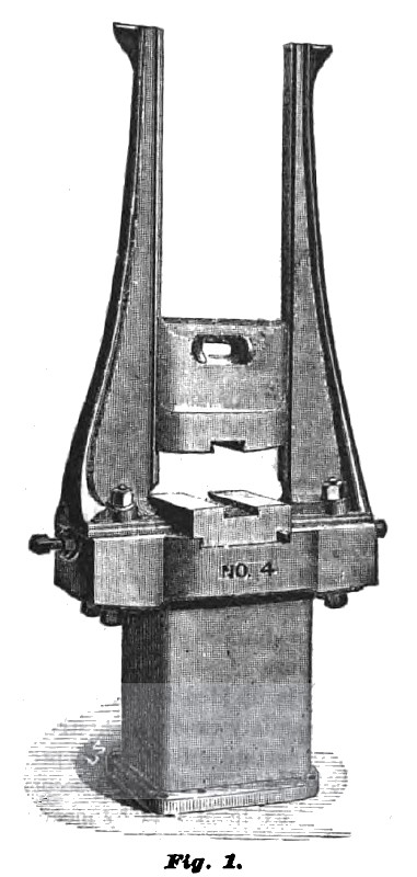
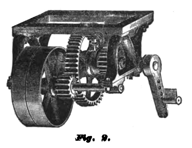
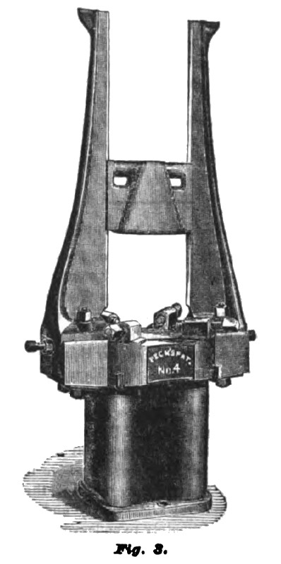
Our illustrations represent machines in which this principle is carefully followed. Fig. 1 shows the drop press for forging; Fig. 2 its lifter above it; Fig. 3 is the standard machine for stamping sheet metals.
The drop for forging (Fig. 1) does not differ materially from others in use, except in the manner of attaching the guides to the anvil, so as to insure their accuracy and durability.
These machines are made of all sizes up to ten tons weight.
The lifter (Fig. 2) differs from all others in its manner of raising the hammer, which is by a crank motion, which takes it from a state of rest with a slow movement, increasing its velocity until it reaches its centre, when it as gradually brings it to rest, avoiding shocks and insuring a uniform height of lift, and of course a uniform blow, whether the speed be uniform or not. These lifters are made to raise hammers weighing from 50 to 2000 pounds to heights from 18 to 30 inches, delivering from 60 to 85 blows per minute, and are claimed to run with less power, to give a heavier blow with the same weight' of hammer, and to work faster and with less expense for repairs than any other in the market. It can always be relied upon to catch the rebound of the hammer without strain or injury to its machine. They can be applied to any drop in use.
The main features of the drop for stamping sheet metals (Fig. 3) are the manner of securing and adjusting the guides and the patent poppets for holding the die in place. These drops are made in all sizes, the size of die-bed varying from 6 to 36 inches, and are used for all kinds of plain and ornamental stamping
The castings are made from the Salisbury charcoal iron, (the strongest iron in the market,) and are much heavier than those of most makers, with the same die space. The guide rods are so fitted to the anvil as to insure their remaining truly perpendicular to the anvil face, and so heavily bolted as not to be affected by the jar caused by the fall of the hammer upon the anvil or die. The patent poppet heads secure a perfect range and uniform pitch to the poppet screws for holding the die in place, which it is impossible to attain by the common methods, and without which the trouble of setting and securing the dies is very great. There are no attachments bolted to the hammer to constantly trouble by breaking where it is impossible to make bolts stand.
The lifting device is entirely disconnected with the drop rods, and thus the jar caused by the fall of the hammer upon the anvil or die cannot derange the lifter, and the action of the lifter will not throw the guide rods out of true, as they will surely do if connected.
Among the other advantages claimed for this machine are, that less power is required to run it than is needed to run any other drop press, the mode of applying the power being more economical, and the friction less; it gives a heavier blow with the same weight of hammer, the hammer falling entirely free, and its whole weight being therefore effective, which (with a single exception) is not the case with any other machine; it works faster, giving twice or thief times as many blows to the minute as any other machine; when the hammer bounds in consequence of a stroke, it is caught, and prevented from falling upon the work until it descends, in regular course to strike a blow—in other words, the machine catches the rebound of the hammer, and prevents it from giving a false strode. This feature renders it eminently suitable for ornamental work, as it will not fall on the work when it has been jarred from its place by a stroke and spoil the impression which that stroke has made. The rebound of the hammer is caught without subjecting the machine to any violence, or in any way exposing it to be broken or damaged; a result which no other machine has yet attained, and which, until the invention of this, was held to be impracticable. Being made in the best manner, and of the best materials, it is not liable to get out of order and is kept in repair at a mere nominal expense.
Further information may be obtained of the manufacturers, Messrs. Milo, Peck & Co., No. 157 Temple Street, New-Haven, Ct.
US Patent: 17,411
http://www.datamp.org/patents/displayPatent.php?number=17411&typeCode=0 |
|
 1872 Milo Peck & Co., Drop Press (Fig. 1)
 1872 Milo Peck & Co., Drop Press (Fig. 2)
 1872 Milo Peck & Co., Drop Press (Fig. 3)
|
|