|
Title: |
1911 Article-Hendey Machine Co., Cone Headstock for Engine Lathes |
|
Source: |
Machine Tools Commonly Employed In Modern Engineering Workshop, V1, 1911, pgs. 15-17 |
|
Insert Date: |
3/17/2020 8:33:56 PM |
The Fast Headstock
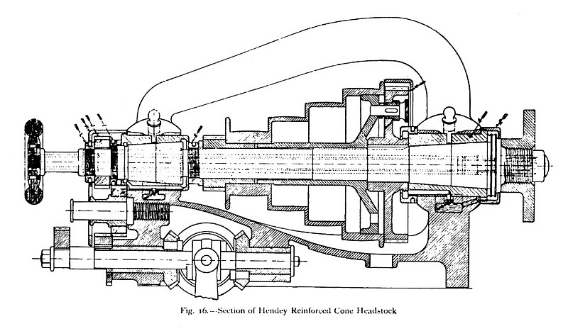
A sectional view of the cone - pulley type of fast head- stock is given in fig. 16, which shows the very strong construction of the housings and the rigid bar connection of the front and rear bearings peculiar to the Hendey lathes. This bar reinforcement gives great rigidity to the head and enables it fully to support the spindle under the heavy - duty conditions involved in the use of modern steels. In the ordinary type of lathe head, where the housings are not tied together, there is a tendency for the front housing to be bent backwards when heavy cuts are being taken, with the result that the spindle is partly bound. By means of the bar connection the front housing receives some support from the rear housing, which, owing to its lesser height and the greater strength of the bar at the small end of the cone, is of ample strength, and the tendency to bind the running spindle is avoided.
The housings and bearings are well rounded, and.it will be noted from the section that there is continuous metal under the cone pulley, and that the head has, therefore, the greatest possible rigidity. The spindle has taper bearings of large diameter for the swing of the lathe, and the bushes are cylindrical externally and not slotted, as is sometimes done for adjusting purposes. At the front bearing the bush is held in position between the flange at the front end and the screwed cap at the rear. The front journal and the thrust collar are so proportioned that the wear of the combined surface is uniform, and the use of an adjustable bush, to remove slackness due to wear, is avoided. Endwise forward motion of the spindle is adjusted solely by means of the end screwed ring L. In the case of the rear bearing the bush is prevented from moving forwards by its end flange, and from moving back by the collars and screwed ring 1 and the wheel j which abuts against the ring L of the spindle. The rear journal is keyed to the spindle and is capable of being moved longitudinally forwards or backwards by means of the screwed ring I, and thus any slackness of the former can be readily adjusted. The face gear m is keyed to the spindle while the coned pulley, with its driving pinion, runs loosely. By means of the screwed collar e, the face wheel can be moved forward until it just bears against the front bearing, and until all unnecessary end shake of the pulley is eliminated. As is usual in back-gear designs of headstocks, the cone pulley, driven by the belt, is coupled to the face wheel m of the spindle either directly, by means of the locking pin shown inserted in the sectional view (fig. 16), or indirectly, through the back gearing, which transmits the motion of the cone from the driving pinion at the left end to the face wheel of the spindle. Self- oiling arrangements are provided throughout, and in the section the oil wells and the oiling rings in each of the main housings are clearly indicated. These rings revolve with the spindle and cause a constant flow of oil to the bearings as long as the spindle is revolving. |
|
 1911 Hendey Machine Co., Cone Headstock for Engine Lathes
|
|