|
Title: |
1911 Article-Hendey Machine Co.-Headstock & Feed Gearbox for Engine Lathes |
|
Source: |
Machine Tools Commonly Employed In Modern Engineering Workshop, V1, 1911, pgs. 16-19 |
|
Insert Date: |
3/17/2020 8:48:52 PM |
Screwing and Feed Mechanism
At the left end of the bed there is situated a compound gear box which controls the speed of rotation of the feed screw, placed at the front of the bed in the customary position. Parallel with, but beneath the lead screw, there is provided a slotted rod the partial rotation of which, by means of the hand lever at the right side of the apron, causes the lead screw to rotate in the reverse direction, while the direction of the lathe spindle rotation remains unaltered. A third rod, provided with adjustable stop pieces, serves to disengage the feed when the saddle reaches a predetermined position.
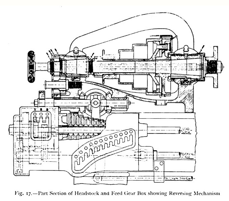
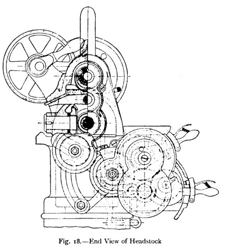
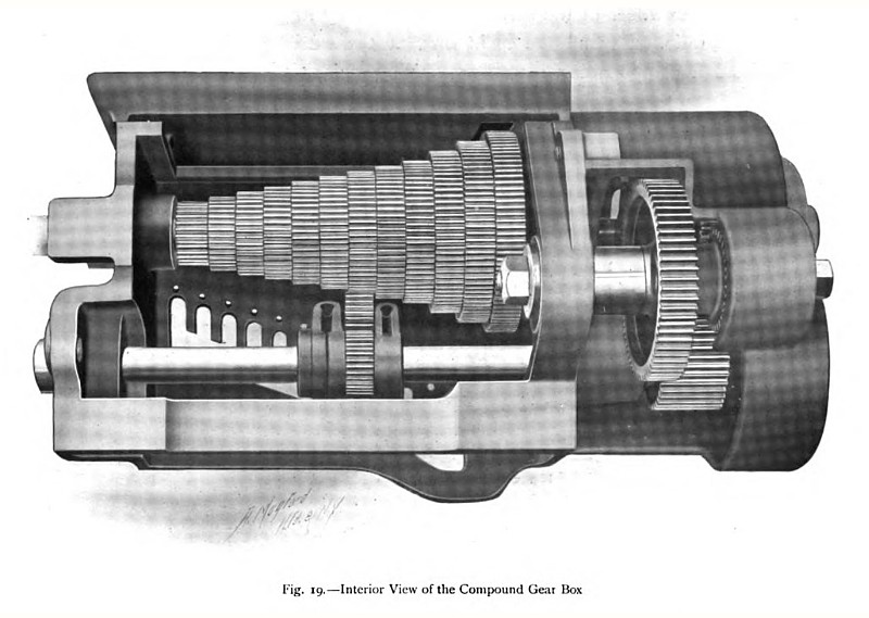
Side and end part sectional views of the headstock and gears are shown in figs. 17 and 18, and a separate general view of the combined gear boxes is illustrated in fig. 19. Referring to these views, it will be seen that the main gear box at the left hand of fig. 19 consists of the well-known arrangement of gear wheels — in this particular example, twelve in number — carried together upon the lead screw shaft, and of a pinion capable of being moved along a slotted shaft which is driven through gearing from the cone-pulley spindle. An idle wheel, in constant mesh with the driving pinion, is so arranged that it can be rocked or swung about the driving- shaft axis into mesh with the gear wheel opposite which the driving pinion is placed. When it is desired to change the lead screw feed, the lever on the face of the main gear box must first be lowered until the idle wheel, referred to above, is disengaged, and the lever must then be moved sideways into the notch opposite the desired feed, which is marked on the nameplate above the box. This side movement brings the driving pinion opposite the correct gear wheel, and it then only remains to raise the lever and swing the idle wheel into mesh. In this way any one of twelve gear ratios can be obtained while the machine is working. It will be evident that the gear ratio is determined by the constant diameter of the driving pinion and by the diameter of the particular gear wheel of the series being driven by it, and that the idle wheel does not affect the ratio. Beyond the main box, at the extreme left end of the machine, there is fitted a compounding gear box which provides three widely different speeds governing the speeds of the main box. Thus, each speed of the main gear box can be varied in three degrees by placing the latched handle of the compounding box in one or other of the three slots provided for it. Thirty-six speeds are therefore obtainable by varying the positions of the two levers, and the arrangement is such that no speed is duplicated, and that the changes are of a practically uniform amount.
This range of feeds is not the limit of the machine, because additional gears can be inserted in the train of wheels as on any ordinary lathe, and, since any single gear can be varied through the entire range of thirty - six speeds, the number of threads or speeds that can be obtained is practically unlimited.
The special apron -reversing mechanism and the automatic stop rod are of particular value when cutting screw threads, as the cutting tool may be stopped at, or started from, a shoulder with ease and certainty without danger of breaking the tool point or damaging the work by overrunning. When the handle at the right of the apron is operated, the reversing rod (fig. 17) rotates and moves a pivoted lever, which controls a double-faced clutch on the gearbox driving spindle, shown in the illustration. When the lever is displaced to the left or the right, the shaft is clutched to one or other of two oppositely rotating wheels driven from the cone spindle, and the rotation of the lead screw is thus reversed. The carriage can also be quickly returned, when required, by hand in the ordinary way after opening the half- nuts which engage the lead screw. The automatic stop rod, for regulating the travel of the carriage, is shown in position beneath the reversing rod. When the carriage touches one or other of the adjustable stop pieces, already referred to, the rod is carried endwise, and the clutch lever, to which it is coupled, is thus automatically placed in the declutched position. |
|
 1911 Hendey Machine Co.-Headstock & Feed Gearbox for Engine Lathes
 1911 Hendey Machine Co.-End View of Headstock for Engine Lathes
 1911 Hendey Machine Co.-Interior View of the Compound Gear Box for Engine Lathes
|
|