|
Title: |
1908 Image-Niles-Bement-Pond Co.-14 ft. Planing Machine (Part 1) |
|
Source: |
Engineering Magazine, V 85, 17 Apr 1908, plate xxxiii & xxxiv; pgs. 525-526 |
|
Insert Date: |
3/19/2020 9:39:51 PM |
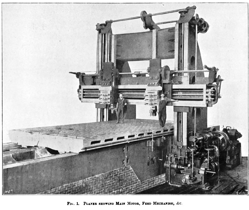
A heavy machine-tool embodying several interesting features is illustrated on Plates XXXIII. and XXXIV., and on this page. This machine, built by the Niles-Bement-Pond Company, Philadelphia, is, in general effect, an extremely large planer, but it is provided with several additional movements to those found on standard machines. For instance, each head is fitted with a slotter bar independently driven by rack, giving a cutting speed that is practically constant from one end of the stroke to the other, and a quick return. Through motor and change gears, the cutting and return speeds can be changed as desired. Again, each head is arranged for transverse planing, having & planing movement across the bed which can be varied within desired limits, and having a quick return.
These movements for slotting and transverse planing make it necessary to throw out of gear the regular table driving mechanism and to connect up to a separate feed motion, which is entirely distinct from the regular feed motion. This throwing out of gear of the driving mechanism means, however, nothing more than that pneumatic driving-clutches are thrown into, and left in, their idle position.
The distance between uprights is 14 ft. 4 in., the maximum distance from the table to the bottom of the cross-slide is 12 ft. 2 in. ; the maximum stroke of table is 30 ft., the maximum stroke of slotter-bar is 8 ft., the total width of bed 13 ft., and the length of bed 60 ft. The table-ways are each 15 in. in width, the tool-slides 4 ft., with 7 ft. 8 in. face for the vertical traverse of the cross-slide. The cross-slide is long enough to admit full traverse of either head between the posts. The face of each upright is 2 ft. 6 in. across. The vertical height of the cross-slide, including the top rib bracing, is 5 ft. The total weight of the machine is 845,000 lb.
The main driving-motor is 100 horse-power, the slotting and cross planing motor is 50 horse power, the lifting motor to the cross-slide 20 horse power, and the traverse motor for the heads on the cross slide 7½ horsepower. The machine is fitted with its own air-compressor driven by a 30-horse-power motor, thus making it independent of the air-supply in the shop, to which, however, it can be connected if desirable. A complete switchboard is furnished for control of all the motors.
The cutting and return speeds are variable through the motor, which has a 1 to 1¼ variation, and further range is obtained by change-gears. The cutting speeds are 14 ft. to 25 ft. per minute and return speeds 52½ ft. to 65½ ft. per minute. The same style of drive is used for slotting, giving a cutting speed of 18½ ft. to 30 ft., and return speed of 57 ft. to 71 ft. per minute. The cutting speed for cross planing is 11½ ft. to 19 ft., and return speed 35 ft. to 43½ ft. The cross-traverse speed to the heads is 50 in. a minute, and the vertical speed for raising and lowering cross-slide is 26 in. a minute.
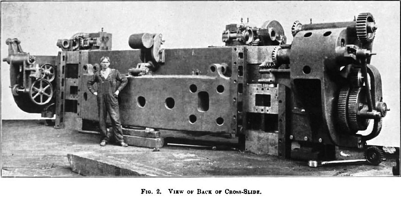
Of our illustrations, Fig. 1, Plate XXXIII., shows the completed planer on the side of the main driving- motor. Fig. 2 shows a back view of the cross slide.
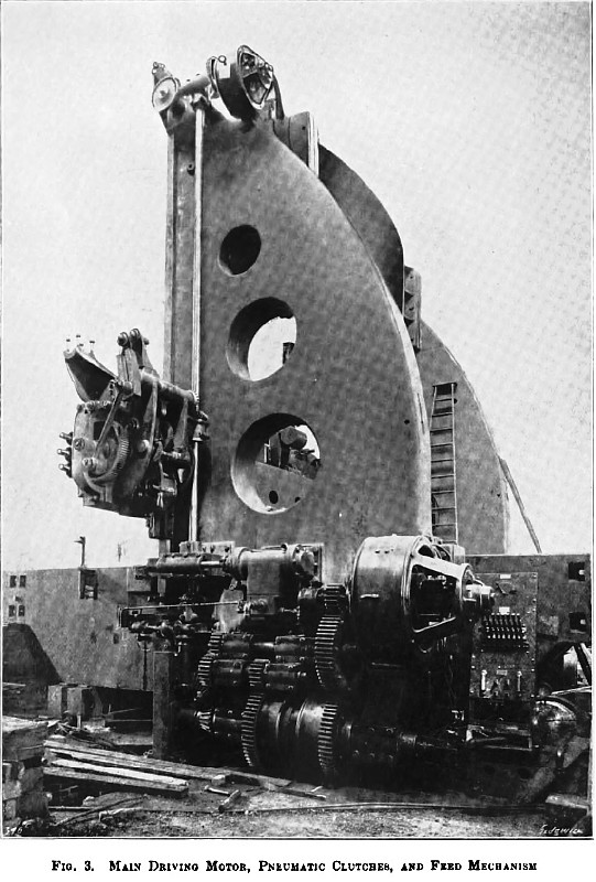
Fig. 3, Plate XXXIV., show's another view of the driving-gear and feed mechanism, Fig. 4 the driving-pinions, and Fig. 5 the tool-holder. In Fig. 6, above, is given a view of the slotter drive at the ease of the further of the two uprights in Fig. 1.
The main drive from the 100-horse-power motor is clearly shown in Figs. 1 and 3, Plates XXXIII. and XXXIV., being through gearing to the pneumatic re-versing clutches at the base of the upright. The speed of these clutches can be varied, as stated above, to some extent by changing the speed of the motor, and a greater variation is obtained by the simple reversal of two change-gears. The pneumatic clutches, which are also shown in these illustrations, are encased, and are of the N.-P.-B. multiple friction-disc type. These clutches are operated by compressed air furnished by the air- compressor and motor previously referred to. The stopping, starting, and reversal of the table are done by means of a small valve moved by hand, which controls satisfactorily the power given out by the large driving-motor. It is scarcely necessary to remark that with such large powers and great masses belt drives would be quite impracticable. From this point of the drive on to the rack the train is practically similar in every respect to that found on any planer, except, of course, that in this instance it is exceptionally heavy and powerful. It is of steel throughout, the two bull pinions being out half pitch apart in order to give smoothness of motion. The gears are connected by a sleeve, and sleeve and gear turn on the shaft, which is stationary. The shaft can be drawn out endwise, and the centre bearing is capped, so that removal of gearing is comparatively easy. These gears are shown in Fig. 4, Plate XXXIV.
Among other many new features, not the least interesting is the pneumatic feed. The feed for the cross-heads is very clearly shown in Figs. 1 and 3. On the side of the upright just above the gearing is a cylinder with piston - rod extending to the left. This rod carries a rack, in gear with a pinion near the bottom of the vertical feed-shaft. This vertical shaft, by means of bevel gears, transmits motion through a horizontal shaft to the vertical feed-shaft on the left-hand upright—viz., to the round shaft to be seen in Fig. 6, page 528. The movement of these feed-shafts is constant at all times, and variation in amount and direction of head feeds is obtained by adjusting the connecting-rod in the slotted cranks on the ends of the cross-slide. These cranks are graduated in such a way that definite cross and vertical feeds can be obtained, and, by using at the same time the cranks on both sides, an angular feed can be given to the tool, which is at times desirable. The valve for controlling the air to the feed cylinder is thrown over automatically at each end of the stroke, this movement being derived from the main driving-gear train to the table, or from the slotter gearing, when slotting is being done. To throw the feed out of gear, it is simply necessary to close a valve, catting off the air-supply. In Fig. 1 the feed for the table gears, when slotting or transverse planing, is shown directly in front, and at the base of, the upright. It operates practically in the same manner as the feed for the cross-head previously described, except that variation in stroke or amount of feed is obtained by an adjustable stop, which regulate the amount of movement of the piston in the cylinder. This adjustment is made by the right-hand of the two hand-wheels shown, the left-hand one being for connecting and disconnecting this feed mechanism to or from the main drive.
The drive on the opposite upright is shown in Fig. 6, page 625. For the main drive the power is carried through the upright into the bed, while for the slotter drive it is, as shown, transmitted to the vertical square shaft, and thence by bevels and spur-gearing to the horizontal square shaft running along the top of the cross-slide. The pinion on this shaft drives the large gear, of which, however, only the casing can be seen in Figs. 1 and 5, and the rack- pinion which gears into the back of the slotting- bar is on the shaft with this gear. The pinion on the square shaft is a sliding one and can be thrown in or out of gear as desired, so that either or both bars can be used. The device for controlling the length of stroke is very clearly shown in Fig-6, page 525—namely, the disc just above the motor. This disc is driven from the main train of slotter gearing, and the adjustable stops on its periphery can be set at any desired point and effect the reversal in the same way as dogs on the side of a planer-table. Near the bottom of the squire vertical shaft in Fig. 6 can be seen the bevel gear on the end of a horizontal shaft which goes across the bed and which can be connected to the mechanism operating the valve of the feed cylinder on the opposite side, as mentioned in the description of the feed for the heads.
In Fig. 1 can be seen a small vertical shaft, where the reversing hand-lever of a standard planer is usually found. It will be noticed that there are two sockets at the upper end, in one of which is a handle. The upper socket is connected to a shaft which runs down to the lower of the two levers or cranks at its bottom extremity. This is the hand control of the slotter. The method of connection of this control may he followed quite clearly, starting as shown in Fig. 1. From here it passes through the bed and comes out on the opposite side. It is then transmitted by the curved connecting-rod running in back of the upright to a spindle passing out through the upright below the slotter-reversing mechanism at the reversing disc (Fig. 6). The lower socket of the two on the 6mall vertical shaft is the one that controls the movement of the table when regular planing is being done; it is connected (Fig. 1) by lever and rods to the reversing dog on the bed on both sides. Only one handle is furnished for each side, and thus mistakes arising from throwing the wrong lever are avoided.
Owing to the great weight and large dimensions, the bed being 73 in. at its deepest part, it was impracticable, both from a manufacturing and a shipping standpoint, to make the bed or table in one piece; they were, therefore, divided to bring them within reasonable limits. The central section of the bed is divided longitudinally into three parts, and the two end sections into two parts, or seven parts in all. The total weight of the bed is about 275,000 lb. The table is made in two sections divided longitudinally in the centre, and its total weight is about 140,000 lb. The holes in the table for stop-bolts, &c., run clear through the upper plate, below which is a second plate, without openings, extending the entire width of the table, which catches all the chips. These chips can then be removed through the side openings of the table, which are clearly shown in Fig. 1.
The motor for the fast traverse of the heads is shown on the end of the cross-slide in Fig. 3. The reversing is done through friction clutches, and a safety arrangement is provided which prevents throwing in the fast traverse and the feed mechanism at the same time. The cross-slide lifting motor is situated at the top of the upright, as shown in Figs. 1 and 3. This motor is connected at all times to the elevating-screws, and is stopped, started, and reversed electrically.
On the end of the table, in Fig. 1, are shown finished pads over the V and flat ways. These are to carry the heads for truing up the ways when worn out of alignment. The method is as follows:—The table is raised, say ¼ in. above the ways, and supported in this position on sliding-blocks fitting small auxiliary V-ways, which are used only for this purpose. The truing heads being fastened to the end of the table, the ways are trued up from the centre to the end. The heads are then placed on the opposite end of the table, and the remaining portion of the ways finished. Near the centre of the bed there are pockets in the ways in which these same truing heads are then placed, and the table is in its turn planed up in a similar manner. The accuracy, of course, of the finished work is dependent entirely upon the accuracy of the small auxiliary ways, and these are finished and erected with great care. They are placed just inside the flatways. It will be noticed that the table guides extend down inside the V’s and flatways a short distance. This is done to prevent any risk of side movement under heavy cuts or transverse planing.
The elevating-screws for the cross-slide are firmly held at top and bottom, and the nut in the cross-slide sets into a shouldered end in a square pocket. It is expected that this will give ample provision for taking up the thrust of the Blotter bar satisfactorily; but if any loosening or trouble is experienced, arrangements have been made so that the slide can be firmly braced to the uprights while the machine is working in this way.
In Fig. 5 a view of one of the tool-boxes is given, which shows their size very clearly. The holder swivels, and adjustment is made by worm-gear working on the quadrant shown just above the holder. Fig. 2 shows the back of the massive cross-slide. In order to ship the uprights of this machine, a flat car was employed specially strengthened with I-beams. These parts alone weighed about 110,000 lb.
From Fig. 7 a fair idea of the size of this planer may be obtained, both from the comparative size of the men, and from the number who have managed to include themselves in the photograph. |
|
 1908 Niles-Bement-Pond Co.-14 ft. Planing Machine
 1908 Niles-Bement-Pond Co.-14 ft. Planing Machine (Back of Cross-Slide)
 1908 Niles-Bement-Pond Co.-14 ft. Planing Machine (Main Driving Motor)
|
|