|
Title: |
1911 Article-Hetherington, John, & Sons, Ltd., Railway Wheel Lathe |
|
Source: |
Machine Tools Commonly Employed In Modern Engineering Workshop, V1, 1911, pgs. 37-38 |
|
Insert Date: |
4/2/2020 12:13:33 PM |
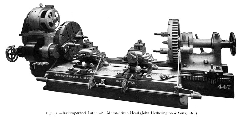
Another example of a railway-wheel lathe, made by John Hetherington & Sons, Limited, of Manchester, is illustrated in fig. 41. In general arrangement the machine resembles the one already described, but it differs considerably in the details of construction. The bed-plate is of a broad box pattern provided with wrought-iron cover plates, and is provided with T slots for the bolting down of the headstocks and the base-plates of the saddles. The large-diameter main driving shaft, upon which are mounted the face-plate driving pinions, is of steel, and is carried within the frame of the bed upon gun-metal bushed bearings. With the arrangements provided it is possible to drive the two face -plates together or separately, either through single or treble gearing, and the machine is therefore adapted to turn a pair of wheels upon an axle without torsion, or to bore two tyres, or boss and bore a pair of wheels. Since the headstocks may be driven independently and at different speeds, it is also possible to carry on different boring and surfacing operations upon work on the two face-plates, such as might be done on two separate surfacing lathes of the type already described. In the example illustrated the driving is done by an electric motor mounted above the fast- headstock; but, if desired, a single fast-and-loose pulley drive may be substituted. Six spindle speed variations are obtainable by suitably operating the indexed hand wheel, at the extreme left of the illustration, and the levers on the headstock, and, as has been already stated, the gearing is so arranged that the headstocks may be driven independently at different speeds. Compound tool rests fitted with all necessary motions and adjustments are provided. Thus the bases and standards may be adjusted in both directions along and across the bed, and the top transverse slides can be swiveled upon the lower longitudinal slides, thus enabling the former to be angled without altering the latter. A rocking shaft, with the customary quadrants, chains, ratchets, and weights, is provided for simultaneously operating the slide rests.
In the particular lathe illustrated the diameters of the face-plates are each 4 ft. 6 in., the height of the centres being 2 ft. 3 in., and the available distance between centres 8 ft. When driven by a constant speed belt or by electric motor, approximately 23 B.H.P. are required for the regular work of the machine. The maximum cutting speed on the maximum diameter is about 30 ft. per min., and the minimum speed on the maximum diameter is 15 ft. per min. |
|
 1911 Hetherington, John, & Sons, Ltd., Railway Wheel Lathe
|
|