|
Title: |
1911 Article-Cunliffe & Croom, Ltd., Metal Planing Machine |
|
Source: |
Machine Tools Commonly Employed In Modern Engineering Workshop, V2, 1911, pgs. 42-44 |
|
Insert Date: |
5/16/2020 9:48:16 PM |
|
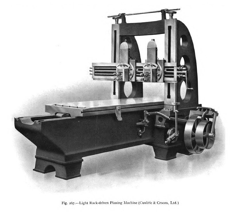
In fig. 267 is illustrated a horizontal planing machine, constructed by Cunliffe & Croom, Ltd., of Manchester, in which the table is driven by means of a single rack and spur wheel. The bed of the machine is deep and strong, and is provided on its upper face with V grooves, along which the table is moved by the rack-and-pinion gearing, the same train of gears being used for traversing the table in both directions. On the driving shaft two pulleys of different diameters are mounted, the diameter of the large pulley being such as to drive the table during the return stroke at a speed three and a quarter times that of the forward or cutting stroke. As the same power is provided to drive the table forward and to return it, there is no shock due to a variation of the driving power at the reversals of the motion. Tappets on the side of the table the reversing gear at each end of the stroke and shift the driving belts from the loose to the driving pulleys, as the case may be. These tappets can be set in any position on the side of the bed, so as to limit the stroke to the required amount. The uprights of the machine between which the bed passes are of a strong box construction, braced together at the top. On the machined faces of the uprights is mounted a horizontal cross rail carrying a pair of toolboxes, which can be moved both vertically and horizontally. Hand gear, consisting of two screws, one in each upright, connected at the top by a cross shaft and bevel gearing, is provided for raising and lowering the cross rail to suit the work on the table, and the screws are provided with ball bearings to reduce the friction and facilitate the motion. At the side of the right- hand upright there is mounted a vertical rack, reciprocated by means of a crank disk, the throw of which can be varied to suit the desired feed. The rack engages a pinion on the toolbox feed shaft, mounted in the cross rail, and the same rack gear is employed for feeding the tool either vertically or horizontally. Check nuts are provided on the vertical-feed screws of the tool slides, to prevent them from rising at the commencement of the cut. The feed motion is so arranged that the cut can be altered at either end of the stroke and any alteration of the transverse feed, from the finest to the broadest cut, can be made while the machine is running. |
|
 1911 Cunliffe & Croom, Ltd., Metal Planing Machine
|
|