|
Title: |
1911 Article-Jones & Lamson Machine Co., Flat Turret Lathe, Heads & Bar Chuck |
|
Source: |
Machine Tools Commonly Employed In Modern Engineering Workshop, V1, 1911, pg. 82-83 |
|
Insert Date: |
4/17/2022 1:38:04 PM |
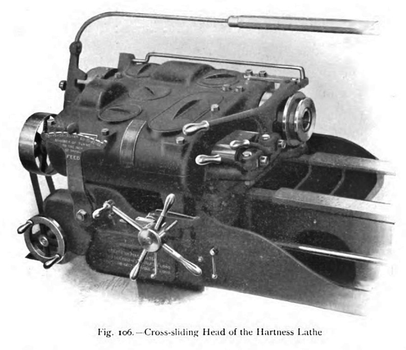
An external view of the cross-sliding head is given in fig. 106, and in fig. 107. The head is shown with the cover removed to expose the variable-speed gears. Power is communicated from a simple overhead shaft, or from a constant-speed motor to the single pulley, which therefore runs at a constant speed, and transmits a constant- powered drive to the spindle. This driving pulley is keyed to the first spindle, the three driving pinions of which mesh with spur wheels carried loosely on the second or speed-variator shaft. When the speed-variator handle is moved into one or the other of three positions, of the three driven wheels on the second shaft is clutched, and the second shaft therefore runs at three speeds, determined by the position of the variator handle. The motion of the second shaft is communicated to the third shaft, upon which are loosely mounted three change wheels, each capable of being similarly operated by moving the back-gear lever into one of its three positions. By suitably operating the speed variator and the back-gear lever, nine different speeds can immediately be obtained. The motion of the gears on the second shaft is communicated to the large spur wheels shown on the spindle. One of these wheels is driven in the forward direction, and the other backwards, and the clutch placed between them is controlled by the shipper, indicated in the illustrations. Thus, when the shipper is in the mid position, the clutch is disengaged from both wheels, and the spindle remains stationary. When the shipper is moved endwise, the clutch engages the forward or the backward rotating wheel, as the case may be, and the spindle therefore rotates in a corresponding direction, and at a speed determined by the positions of the two speed levers. All the mechanism of the headstock is entirely enclosed in a casing, the lower half of which is filled with oil, while the top half serves as a cover and prevents the entrance of dirt and the leakage of oil. Not only are the lower halves of the gear wheels and the running clutches submerged in oil, but the shaft bearings, and also the main bearings, are lubricated in the same manner. Efficient lubrication is essential in any machine intended for the use of high-speed steel tools, as the run- ning speeds are very considerable.
Guide ways are machined accurately at right angles to the shears of the bed, and upon these guides the sliding headstock is traversed transversely to the tool held in the turret. Ten adjustable stops are mounted in a revolvable holder, which may be rotated by suitably operating the star handwheel, shown at the front of the bed under the headstock. These ten stops positively limit the travel of the sliding cross- head, whether the head is traversed by power or by hand. The power-feed mechanism the head until it reaches the stop, which has been set in the controlling position, and holds it there until it is released by hand. Thus a definite feeding pressure is always obtained, and the same uniformity of pressure is secured in the case of hand feeding by providing a sensitive indicator, which shows when the operator has exerted the necessary force.
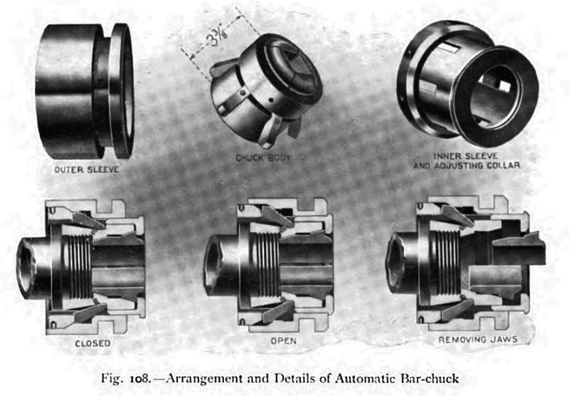
When the machine is arranged for bar work, the automatic chuck represented in fig. 108 is mounted upon the nose of the hollow spindle and is opened and closed by means of the hand chuck lever, indicated in the general view of the machine. In the illustration the three sections show the arrangement of the parts in the closed and the open condition, and also, the operation of removing the jaws preparatory to inserting others of a different bore. The main portions of the chuck are represented separately in the upper part of the figure. When the outer sleeve is moved inwards towards the head, the loose strut pieces which abut against the chuck body at one end, and the adjustable collar of the inner sleeve at the other, are forced downwards, and move the inner sleeve lengthwise towards the left. The outer flange of this sleeve bears against the end of the jaws, which are accordingly driven slightly in- wards, and caused to close within the conical seat of the chuck body. By means of the screwed adjustable collar, against which the struts bear, the pressure of the jaws can be varied; and when the collar is screwed back, as shown in the third section of the illustration, the inner sleeve can be moved outwards, and the jaws be removed. |
|
 1911 Jones & Lamson Machine Co., Flat Turret Lathe, Cross Sliding Head
 1911 Jones & Lamson Machine Co., Flat Turret Lathe, All Gear Head
 1911 Jones & Lamson Machine Co., Flat Turret Lathe, Automatic Bar Chuck
|
|