|
Title: |
1887 Article-Woodbury Engine Co., Steam Engine for Electric Lighting |
|
Source: |
Electrical World, V10, 30 Jul 1887, pg. 53 |
|
Insert Date: |
5/8/2022 9:38:05 PM |
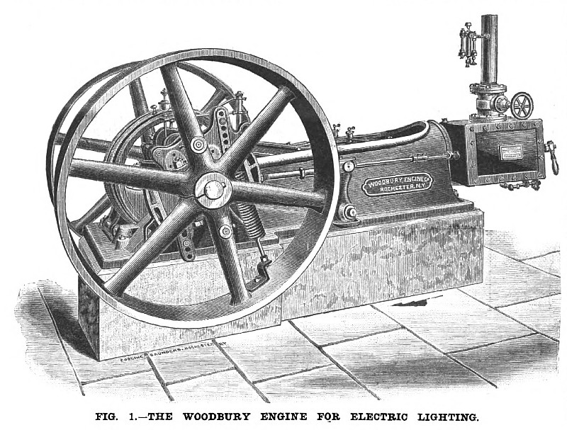
Recognizing the high qualities demanded of an engine employed in electric lighting, both as regards economy and regulation, the Woodbury Engine Company, of Rochester, N. Y., have designed several sizes of engines constructed upon the general type of that shown in the engraving, Fig. 1.
The engine, as will be seen, is of the self-contained, single valve type, and the regulation is effected by an automatic cut off. Two centrifugally acting weights are employed, to one of which the eccentric is attached. The centripetal, or opposing force, is furnished by a single spiral spring, the two weights being connected by a link. The chief characteristic of the governor is in the adjustment, which enables the centrifugal and centripetal forces to be so balanced at all positions that the fluctuations in speed from light to heavy load and with great ranges in steam pressures, are confined within very small limits. This is accomplished in the following manner: The link which connects the spring to the main weight has a series of holes in the weight itself, as shown in Fig. 1. There are seven holes, and the sustaining pin, which takes the strain of the spring, fits through any hole in the weight and the corresponding hole in the link. By shifting the pin, therefore, the tension of the spring can be varied at will and its sensibility increased to such a point that the travel of the valve and admission of steam shall correspond exactly with the load.
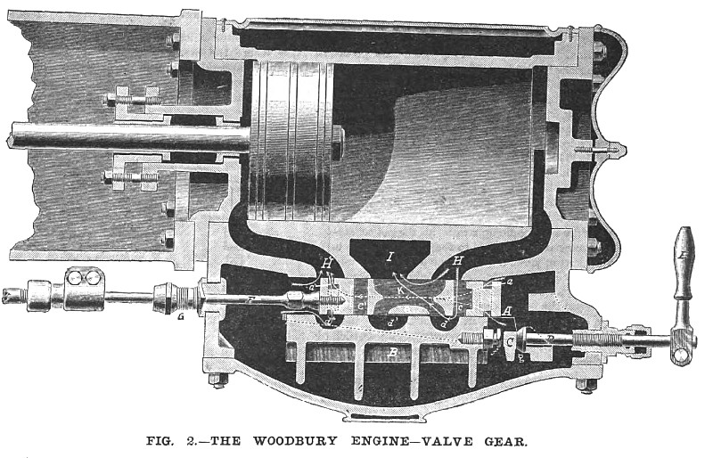
The valve shown in Fig. 2 is of the flat side form and is wholly balanced by a relief plate on the back, so as to work in equilibrium. The relief plate has cavities corresponding with the cylinder face and the valve slides between the two surfaces. The presence on the relief plate comes upon a double or forked wedge at top and bottom, shown in the dotted lines. The longitudinal movement of the wedges controls the relative position of the faces, and the adjustment of the wedges is made by two screws, not shown, which pass loosely through their heads and tap into the relief plate. The handle E and screw D are not for adjustment, but to provide a means of temporarily separating the faces in starting the engine until all of the parts are thoroughly warmed up, when the relief plate is let down into its normal working position by throwing back the handle. The adjusting screws, which operate the double wedge are each provided with a collar, on which are cut one hundred notches and as the movement of the screw to the extent of one notch represents of but 1/10,000 of an inch, the adjustment is micrometrical in its character and is very simply and easily made. There being, however, no pressure upon the faces, the wear is very small in amount and takes place so slowly as to require adjustment but once in several months.
The admission of steam takes place, as will be seen, at four points at the same time. In the position of valve shown, steam is entering past the end of the valve, both directly and through the cavity in the relief plate, whence it passes through an auxiliary steam port a” into the cylinder. Steam is also entering at the opposite end of the valve at two points and passing through supplemental passages into port a’ and cylinder. The cut-off, of course, takes place at four points at once also. For the exhaust, an auxiliary port is provided, so that it takes place at two points, as shown by arrows.
By this means a sharp cut off is insured, and practically full boiler pressure is obtained in the cylinder. The exhaust also is free and without back pressure.
The shaft and pin are formed in one solid forging and the counter-balancing discs are held to the cranks wrought iron clips passing around the cranks and secured with nuts. The cranks are turned off at the end for the discs, which are bored out to fit, and the discs are therefore removable, and when replaced will run true.
All the parts of the various sizes of this engine are designed with a view to durability and economy, and the engines already in operation are said to give excellent results. The Stott Woolen Company, of Stottville, N. Y., have one of them driving its electric light plant, at a speed of 300 revolutions per minute: size 8 X 12. The Edison Company, at Rochester, has ordered one 16 x 20 to run at 200 revolutions. |
|
 1887 Woodbury Engine Co., Steam Engine for Electric Lighting
 1887 Woodbury Engine Co., Woodbury Steam Engine Valve Gear
|
|