|
Title: |
1874 Article-Charles Merrill & Sons-Drop Hammer |
|
Source: |
Industrial Monthly, V5, Oct 1874, pg. 237 |
|
Insert Date: |
7/26/2022 9:57:47 PM |
Improvements in Drop-Hammers
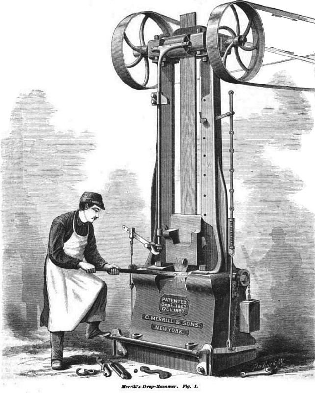
The accompanying engraving is such an excellent representation of one of the drop-hammers designed and constructed by C. Merrill & Sons, of New York, that but little verbal description seems necessary. The tool is a very simple one, and all its mechanism is of a plain and strong description. It is adapted to any kind of work for which drop hammers are employed, but especially for the manufacture of drop forgings, as the blow is sharp and quick, and the hammer is caught to prevent the rebound.
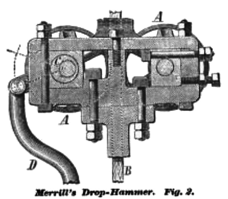
From the elevation and sectional view, Fig. 2, it will be seen that the hammer head, which weighs from 300 to 1,800 pounds, travels between two uprights. To it is attached a board of white oak or other suitable wood, which passes between two smooth friction rolls located in the upper portion of the machine. These rolls revolve in opposite directions, and each is driven by a separate pulley from one driving shaft, with cross and open belts. When they are closed together and pressed against the board, their friction upon each side of the latter raises it, and thus elevates the hammer; then, when the rolls are separated, the head is free to fall by its own gravity. The mechanism by which the operation is effected will be understood in the sectional view, Fig. 2, in which A A are the rolls, and B the board between them.
The shaft, upon which the front roll is keyed, runs in eccentric sleeves (one of which is shown at C), which are placed in stationary boxes. Hence, when these sleeves are rotated a small portion of a circle, the front roll is moved nearer to or further from the rear roll. To the arms of the sleeves is attached a drop-rod, D, which connects with a lever, and the latter with a treadle. Suppose the hammer to be at the upper portion of the frame and to rest upon the latch shown at the right, Fig, 1. This latch, it will be seen, is adjustable and may be pivoted at any elevation and is connected to the treadle bar. When the workman presses the treadle down with his foot, he raises the drop bar, D, and as is evident, at the same time pulls back the latch. Raising the drop bar causes a separation of the rolls; and the latch also being removed, the hammer, being unsupported, falls. At that instant, the blow being delivered, the operator removes his foot from the treadle, the drop rod then falls, and the eccentric sleeve turning the front roll, aided by the pull of the belt, is forced against the board, raising the hammer up again.
If it is desired to give a series of heavy blows, the hammer is allowed to rise to its full height, when the operator, by pressing down on the treadle, raises the rod, separating the rolls as before shown, and the blows are repeated; if, while the hammer is ascending, the operator wishes it to fall, he has only to press the treadle down, which raises the rod, and the hammer will fall. The hammer, as a moment’s consideration will show, follows the motion of the foot; thus short and light or long and heavy blows may be given; or, should the operator not wish to strike the blow after the pushing down of the treadle has release the hammer from the latch and is falling, he has only to raise his foot before it strikes and the pinch coming on the board, the hammer will be stopped and will rise to the top. Both the latch on the right and the dog on the rod are adjustable, to enable the operator to give blows of definite weight on special work. After the hammer has been released from its rest on the latch, a little experience will enable the operator to raise the rod just sufficient to partly take off the pressure of the rolls against the board, which will allow the hammer to fall slowly, and give a blow as light as desired. The machine is under complete control of the operator and is managed with perfect facility. In order to compensate for the gradual wearing down of the plank, the movable box, in which the rear friction pulley has its bearings, is provided with screw-blots, as shown as the right of Fig. 2. The upper of these bolts extend through the box, but the lower ones only to its outer side. After loosening the upper screw-bolts, the lower ones can be turned in, thus pushing the box closer up to the board. Then, by tightening the upper bolts again, the box is rigidly secured in place.
US Patent: 36,459
https://datamp.org/patents/displayPatent.php?number=36459&typeCode=0
US Patent: 69,518
https://datamp.org/patents/displayPatent.php?number=69518&typeCode=0 |
|
 1874 Charles Merrill & Sons-Drop Hammer
 1874 Charles Merrill & Sons-Drop Hammer (Fig. 2)
|
|