|
Title: |
1887 Article-Pedrick & Ayer, Portable Wrist Pin Machine |
|
Source: |
Railroad & Engineering Journal, V61, Aug 1887, pg. 379 |
|
Insert Date: |
2/17/2023 7:51:43 PM |
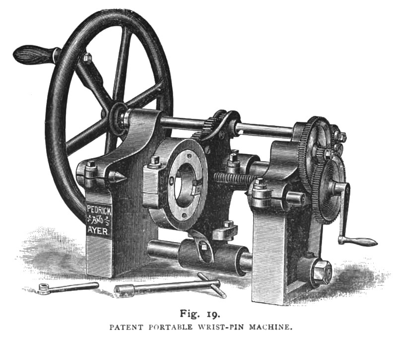
The truing up of a crosshead pin or wrist-pin by hand, or with bent tools in a lathe is a very expensive job. The work performed by the patent portable wrist-pin machine shown in fig. 19. is very important, reducing the cost of this work materially. In the planning of this machine, special has been directed toward securing facility of operation in the limited space available and is readily manipulated and handled by the ordinary workman. It consists of two side castings or housings, held together by two parallel rods, ground true. These rods serve as guides, on which the turning device slides. Between the two guide-rods, a screw is placed, as near as possible to the work, and this screw being turned by gearing on the end of the crank-shaft, becomes an automatic feed, which will operate in either direction; or, for convenience in finishing out the fillets at either end of the wrist-pin, this feed can be thrown out, and the device worked by hand.
The sliding arrangement which carries the annular cutter-head or tool-holder is composed of two parts, held firmly together by four steel collar-bolts, parting line being exactly in line with the guide-rod and feed-screw, and all together are on the center line of the machine.
The cutter-head or tool holder is of steel, and its division allows it to be adjusted around the wrist pin to be turned. Gear teeth, cut out of a portion of its circumference, engage with others, operated by the crank shaft.
In the housings, centres are placed to hold the cross head to be operated on. These centres are in line with the main guide rod, and exactly central to the tool holder.
The tools are inserted in the sides of the tool holder, and are held in place by screws fitted into holes, countersunk for manipulation by a socket wrench, and can be readily taken out to grind.
Special care should be taken in laying out the crossheads to be operated on. See that center marks of sufficient depth are made in the end opposite the intended center of the wrist-pin; then place the cutter-head or tool-holder around the wrist-pin, with tools in, set back. Place the crosshead in the machine, on the centers; adjust the sliding frame on the guide-rods and the work, and the machine is ready.
These machines are also built for stationary use in shops; and those of the stationary type, being driven by power, are adapted to a great range of work. The machine shown in the accompanying cut is of a size intended for general use in locomotive shops, either on new work, or for trueing oval or cut wrist pins. |
|
 Pedrick & Ayer,1887 Portable Wrist Pin Machine
|
|