|
Title: |
1912 Article-Cochrane-Bly Co. Universal Shaper |
|
Source: |
Machinery Oct 1912, pg 142-143-144 |
|
Insert Date: |
9/22/2011 8:03:57 PM |
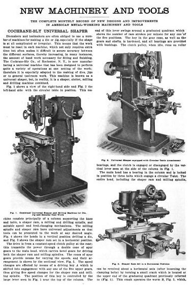
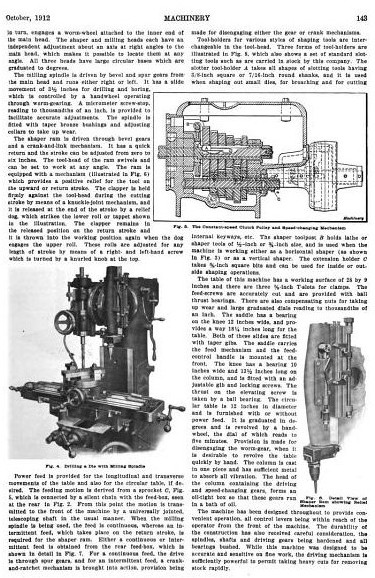
COCHRANE-BLY UNIVERSAL SHAPER — Die-makers and toolmakers are often obliged to use a number of machines for making a die or jig, especially if the shape la at all complicated or irregular. This means that the work must be reset in each machine, which not only requires extra time but often makes it difficult to secure accuracy between the different surfaces, thereby increasing, in many instances, the amount of hand work necessary for fitting and finishing. The Cochrane-Bly Co., of Rochester, N. Y., is now manufacturing a universal machine that has been designed to perform quite a variety of operations at one setting of the work; therefore It is especially adapted to the making of dies, jigs or to general tool-room work. This machine is known as a universal shaper, but, in reality, It is a shaper, slotter, milling and drilling machine combined. Fig. 1 shows a view of the right-hand side and Fig. 2 the left-hand side with the circular table in position. This machine consists principally of a column supporting the knee and table, a shaper ram, a milling and drilling spindle, and suitable speed- and feed-changing mechanisms. The milling spindle and shaper ram have universal adjustments so that tools can be presented to the work at any desired angle. Fig. 4 shows the heads in a vertical position drilling a die, and Fig. 3 shows the shaper ram set in a horizontal position.
The drive is from a constant-speed clutch pulley at the rear; this transmits the power through a double cone of spur gears to the main head, which carries bevel gears for driving both the shaper ram and milling spindles. The cones of spur gears provide means for varying the speeds, and their arrangement is shown by the sectional view. Fig. 5. The speed changes are effected by means of a driving key A which is shifted into engagement with any one of the five upper gears, thus giving five speed changes for the shaper ram and milling spindle. The position of this key is controlled by the large lever seen in Fig. 1 near the top of the column. The end of this lever swings around a graduated quadrant, which shows the number of ram strokes per minute for any one of the five positions. The key in the gear cone, as well as the gears and shafts. Is hardened, and all bearings are provided with bushings. The clutch pulley, when idle, runs on roller bearings, and the clutch is engaged or disengaged by the vertical lever as seen on the column in Fig. 1. The main head has a bearing in the column and is locked in position by three bolts, which engage a circular T-slot. The entire head, including the shaper head and milling spindle, can be revolved about a horizontal axis (after loosening the clamping bolts) by turning a small crank which is located at the upper end of the graduated quadrant previously referred to (Fig. 1). This crank operates the worm B, Fig. 5, which, in turn, engages a worm-wheel attached to the inner end of the main head. The shaper and milling heads each have an independent adjustment about an axis at right angles to the main head, which makes it possible to locate them at any angle. All three heads have large circular bases which are graduated to degrees.
The milling spindle is driven by bevel and spur gears from the main head and runs either right or left. It has a slide movement of 3½ inches for drilling and boring, which is controlled by a handwheel operating through worm-gearing. A micrometer screw-stop, reading to thousandths of an inch, is provided to facilitate accurate adjustments. The spindle is fitted with taper bronze bushings and adjusting collars to take up wear.
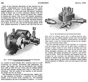
The shaper ram is driven through bevel gears and a crank-and-link mechanism. It has a quick return and the stroke can be adjusted from zero to six inches. The tool-head of the ram swivels and can be set to work at any angle. The ram is equipped with a mechanism (illustrated in Fig. 6) which provides a positive relief for the tool on the upward or return stroke. The clapper is held firmly against the tool-head during the cutting stroke by means of a knuckle-joint mechanism, and it is released at the end of the stroke by a relief dog, which strikes the lower roll or tappet shown in the Illustration. The clapper remains in the released position on the return stroke and it is thrown into the working position again when the dog engages the upper roll. These rolls are adjusted for any length of stroke by means of a right- and left-hand screw, which is turned by a knurled knob at the top. Power feed is provided for the longitudinal and transverse movements of the table and also for the circular table, if desired. The feeding motion is derived from a sprocket C, Fig. 5, which is connected by a silent chain with the feed-box, seen at the rear in Fig. 2. From this point the motion is transmitted to the front of the machine by a universally jointed, telescoping shaft in the usual manner. When the milling spindle is being used, the feed is continuous, whereas an intermittent feed, which takes place on the return stroke, is required for the shaper ram. Either a continuous or intermittent feed is obtained from the rear feed-box, which is shown in detail in Fig. 7. For a continuous feed, the drive is through spur gears, and for an intermittent feed, a crank-and-ratchet mechanism is brought into action, provision being made for disengaging either the gear or crank mechanisms. Tool-holders for various styles of shaping tools are Interchangeable in the tool-head. Three forms of tool-holders are illustrated in Fig. 8, which also shows a set of standard slotting tools such as are carried in stock by this company. The slotter tool-holder A takes all shapes of slotting tools having 3/8-lnch square or 7/16-inch round shanks, and it is used when shaping out small dies, for broaching and for cutting
internal key-ways, etc. The shaper tool-post B holds lathe or shaper tools of ½-inch or ¾-inch size, and is used when the machine is working either as a horizontal shaper (as shown in Fig. 3) or as a vertical shaper. The extension holder C takes 3/8-inch square bits and can be used for inside or outside shaping operations. The table of this machine has a working surface of 28 by 9 Inches and there are three 5/8-inch T-slots for clamps. The feed-screws are accurately cut and are provided with ball thrust bearings. There are also compensating nuts for taking up wear and large graduated dials reading to thousandths of an inch. The saddle has a bearing on the knee 12 inches wide, and provides a way 18 ¼-inches long for the table. Both of these slides are fitted with taper gibs. The saddle carries the feed mechanism and the feed control handle is mounted at the front. The knee has a bearing 10-inches wide and 13½-inches long on the column, and Is fitted with an adjustable gib and locking screws. The thrust on the elevating screw is taken by a ball bearing. The circular table is 12 Inches in diameter and is furnished with or without power feed. It is graduated in degrees and is revolved by a handwheel, the dial of which reads to five minutes. Provision is made for disengaging the worm-gear, when It is desirable to revolve the table quickly by hand. The column is cast in one piece and has sufficient metal to absorb all vibration. The head of the column containing the driving and speed-changing gears, forms an oil-tight box so that these gears run in a bath of oil. The machine has been designed throughout to provide convenient operation, all control levers being within reach of the operator from the front of the machine. The durability of the construction has also received careful consideration, the spindles, shafts and driving gears being hardened and all bearings bushed. While this machine was designed to be accurate and sensitive on fine work, the driving mechanism is sufficiently powerful to permit taking heavy cuts for removing stock rapidly. Some of the principal dimensions of this machine are as follows: Longitudinal travel of the table, 22 inches; transverse movement, 10 inches; vertical adjustment, 18 inches; angular adjustment of the main head, 360 degrees; maximum stroke of shaper ram, 6 inches; maximum distance from end of ram to table, 15 inches; number of speeds, five; number of strokes per minute, from 25 to 150; angular adjustment, 30 degrees each way from the center; maximum distance from end of milling spindle to table, 16 Inches; maximum distance from center of spindle to face of column, 13½ inches; number of taper, No. 9 B. & S.; size of hole through spindle, 17/32 inch; angular adjustment, 45 degrees each way from the center; number of speed changes, five; variation, from 55 to 330 revolutions per minute; micrometer stop adjustment, 3½ inches. The shaper ram has an intermittent feed varying from 0.002 to 0.032 inch per stroke, and the milling spindle has six feed changes varying from 0.004 to 0.048 inch per revolution. The net weight of the machine is 2000 pounds; the height over all, 65 inches. The equipment includes an oil tank and hose; shaper, Blotter and extension tool-holders; a spud-bar for the milling spindle; a set of Blotter tools; wrenches, etc. The following extra equipment can also be furnished, if desired: A circular table with or without power feed; a milling machine vise; draw-rods for the milling spindle; spring collet with bushing and nut; drill chuck; expanding milling arbors; milling machine center; center for circular table; sleeves for the spindle, and a self-contained motor drive. The full universal features of this machine, in conjunction with the various tools which can be used, make it possible to machine a large variety of such work as blanking and forging dies; punches; forming tools, such as are used In turret lathes, automatic machines, etc.; jigs, especially when shaping, milling and boring operations are required; and similar classes of work. While the machine was designed more particularly for the tool-room, the universal features make it possible to handle with the regular equipment and standard tools, a large variety of work which ordinarily would require several machines of different types and also special tools and fixtures. |
|
 1912 Cochrane-Bly Co. Universal Shaper-page 142
 1912 Cochrane-Bly Co. Universal Shaper-page 143
 1912 Cochrane-Bly Co. Universal Shaper-page 144
|
|