|
Title: |
1906 Article-C. Redman & Sons, Belt Shifting Device |
|
Source: |
The Mechanical Engineer, V17, 03 Feb., 1906, pg. 158 |
|
Insert Date: |
3/29/2024 11:51:28 AM |
BELT SHIFTING DEVICE FOR SPEED CONES.
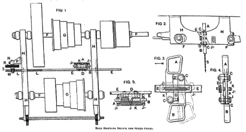
The shifting of bells upon speed cones has chiefly been effected by hand, and in the case of large and powerful driving media a great amount of danger is incurred in the operation, apart from the difficulty and time taken up in effecting the change. A simple and effective device for this purpose has recently been introduced by C. Redman & Sons, of Pioneer Ironworks, Halifax, and is shown in the accompanying illustrations applied to a planing machine. Fig. 1 is a plan view of countershafts with the device applied, Fig. 2 an end view of Fig. 1, Fig. 3 a side elevation of belt forks or loops, Fig. 4 is an end elevation of Fig. 3, and Fig. 5 is a plan of Fig. 3.
Two belt forks A B are employed. One fork encircles the driving portion of the belt, and the other the non-driving portion. These forks hinge upon studs C in a casting D mounted upon a longitudinal sliding bar E; this bar E is situated between, and is moved in a direction parallel with, the countershafts F and speed cones G, and is carried by the hangers H supporting the shafts. The independent movement of each fork in one direction is limited by a stop J, and in the other direction is checked and returned by a spring K connected to studs J, upon the belt forks. The movements of the forks occur alternately, that is, while one fork is prevented from moving in one direction by the stop J, the other fork may move upon its pivot in an opposite direction, but such movement is checked or retarded by the spring K, which tends to return the fork to its original position immediately the tension is removed. The sliding bar E has teeth L upon its upper edge at one end, which engage with a pinion M upon a stud N supported by a bracket P bolted to the countershaft hanger H. The pinion M is operated (to give a horizontal movement to the rod E) by means of chain wheel R and chain S, the latter being of a desired length and within convenient reach of the operator.
The action is as follows: In moving the sliding bar in a certain direction indicated by arrow at Fig. 3, the fork A (that encircling the driving portion of the belt) is held rigid by its stop J, and by the continued movement of the bar E tends to push the belt off the larger diameter pulley of the cone on to a smaller one. While this fork A is traversing the width of the pulley, the other fork B is being acted upon by the non-driven portion of the belt, and moves on its pivot J in direction as shown at dotted lines in Fig. 3, being free to do so, yet putting an increasing tension on the spring K. Immediately the belt w forced off the larger pulley anti become* slack, the second fork B is released and at once returned to its original position by the spring K; the fork B during such return takes up the slack of the belt, and jerks or raises same on to a larger diameter pulley on the driven cone, so effecting the desired change in speed. The movements and actions of the forks or loops are reversed upon the reversal of the direction of movement of the sliding bar.
Patent #GB-190,504,932
https://www.datamp.org/patents/displayPatent.php?number=190504932&typeCode=0&country=GB |
|
 1906 C. Redman & Sons, Belt Shifting Device
|
|