|
Title: |
1890 Article-Holly Mfg. Co., Gaskill Pumping Engine |
|
Source: |
The Steam User 1890 pg xii |
|
Insert Date: |
4/2/2011 12:32:32 PM |
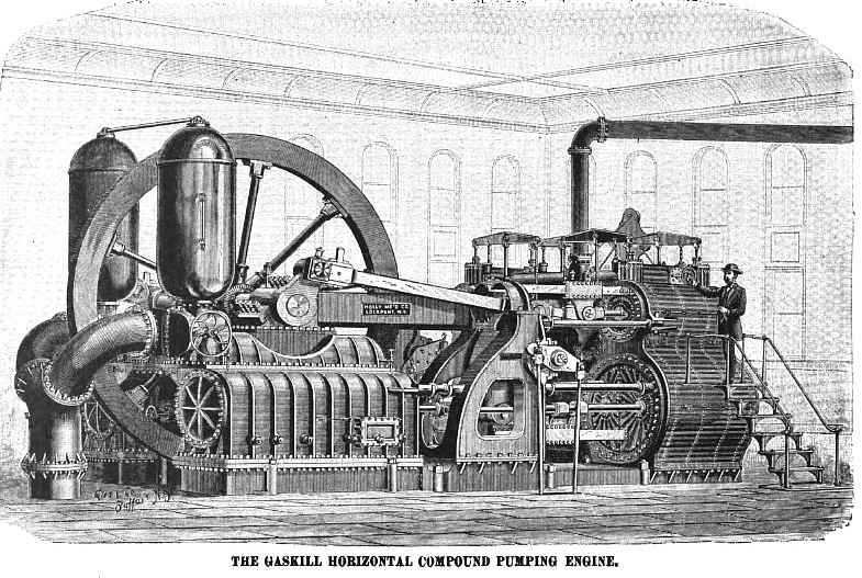
In the design and construction of this engine the inventor, the late H. F. Gaskill, had in view the production of a pumping engine that would combine with the utmost simplicity of construction a first low cost and a high economy.
The contract for the first of these engines built specified that “said pumping engine shall have a pumping capacity to deliver four million United States gallons of water in twenty-four hours against eighty pounds domestic pressure to the square inch at eighteen revolutions per minute, and guarantee that said engine can be run at thirty revolutions per minute with perfect safety; said pumping engine shall, with safety to all its parts, carry a fire pressure of one hundred and forty pounds to the square inch, and develop a duty equal to raising eighty million pounds of water one foot high with one hundred pounds of best coal consumed, and an average daily duty of sixty five million foot-pounds with good merchantable anthracite coal, reasonably free from dirt and slate."
The results of the two separate duty trials, one conducted by J. W. Hill, M.E., and Prof. D.M. Greene, the other by Prof. Chas. T. Porter, show from 106,888,000 to 112,899,983 foot-pounds duty, and the daily record as kept by Engineer David L. Holland, shows the average daily duty for five years to have been over 105,000,000 foot-pounds.
Since this first engine was designed, one hundred and twelve have been sold, ranging in daily capacity from one million to twenty million gallons, with an aggregate capacity of 526,000,000 daily.
Upon the following page is shown an outline engraving of the Gaskill Vertical Triple Compound Pumping Engine. This engine differs from the Gaskill Horizontal Engine by having intermediate receivers between the steam cylinders, and by using the steam in successive expansions between a the three steam cylinders; steam being admitted to the high-pressure cylinder, expanded therein, again expanded in the intermediate cylinder, and finally expanded in the low-pressure cylinder, the low-pressure cylinder having an area about six and one half times that of the high-pressure cylinder. By this means a grade of expansion is obtained ranging from eighteen to twenty-five, and the three steam cylinders assume temperatures which are graded between that of the condenser and that of the boiler; the high temperature steam entering the high-pressure cylinder, which by this arrangement assumes a higher temperature than in ordinary compound engines, is not condensed as rapidly, and consequently a very high duty is obtained.
There are three steam cylinders—one high pressure, one intermediate, and one low pressure. These three cylinders are supported in line upon a heavy framework of cast iron, the framework being bolted to it, and supported by six heavy cast-iron bed plates or girders, which cross the pumping pit and are secured by anchor bolts to the foundations on either side. There are two fly-wheels, one being located on the main shaft between the high-pressure and intermediate pressure cylinders; the other being located on the main shaft between the intermediate-pressure and the low-pressure cylinders. The main shaft is in two parts, each part supporting one fly-wheel, and being in turn supported in two bearings formed upon two of the cast-iron bed plates or girders which cross the pump pit. On the shaft nearest the high-pressure cylinder are placed two cranks at an angle to each other of 120°. To one of these cranks is united, by means of a connecting-rod, the piston-rod of the high-pressure cylinder; to the other is united, by means of a connecting-rod, the piston-rod of the intermediate-pressure cylinder. On the other crank-shaft, and on the portion nearest the low-pressure cylinder, is located, in line with the low-pressure cylinder, another crank. The three cranks above described are attached to the shafts in such a way that their crank-pins form angles to each other of 120°. There is a fourth crank on the shaft nearest the low-pressure cylinder, this crank being located under the intermediate-pressure cylinder, the centre of its crank-pin being placed at an angle of 60° to the crank on the adjacent end of the other shaft. These two cranks which lie under the intermediate-pressure cylinder are connected by a short link, thus coupling the entire shaft into one in such a manner that any faults of alignment are compensated or taken up in the short link connecting the two centre cranks; and the three pistons of the high, intermediate, and low pressure cylinders, being thus connected, through the medium of the shaft and cranks, are compelled to move simultaneously with the rotation of the crank shaft; and, from the manner in which the pistons of the three cylinders are connected to the crank shaft, the different parts of the engine are in perfect balance.
Under the centre of each of the three cylinders above described is placed a single-acting plunger pump. From the bed-plate castings there extend downward twelve wrought-iron tie-rods, which connect the framework of the engine above to the pumps below. These tie-rods extend through the discharge-valve box, a portion of the suction valve-box at the bottom, and through the bed-plate casting and a portion of the framework above. Between the pumps and the bed-plate casting are placed cast-iron struts through which these tie-rods pass. The plungers of the pumps enter through a stuffing-box, or gland, in the centre of the discharge-valve box, passing downward through the centre of the discharge-valve plate into the interior of the suction-box. To reduce friction, the lower end of these plungers is made conical in form. Below the framework of the engine are the twelve tie-rods connecting the framework to the pumps are united by cast-iron beams, and these beams are floored over with cast-iron foot-plates. At this level also is placed an air-pump, which is driven from the upper cross-head of the intermediate pressure cylinder. An iron staircase is provided, giving access to this platform, and an iron staircase also extends from this point to the bottom of the pump well.
This type of engine the Holly Manufacturing Company is prepared to furnish in ten sizes, of capacities ranging from 2,000,000 to 20,000,000 gallons in twenty-four hours, to operate against water pressures ranging from 100 to 300 feet.
The steam cylinders are provided with the Corliss valve gear, and the valves of each steam cylinder are arranged to cut off at any point of stroke, the point of cut-off on each cylinder being adjustable independent of the other; or they can be controlled by the action of a pressure-regulator or ball-governor, depending on whether the service is pumping directly into the mains or pumping into a reservoir. In the latter case a uniform speed is desirable; in the former case a variable speed is desirable in order that the pumping-engine may exactly meet the daily demands for water. |
|
 1890 Holly Mfg. Co., Gaskill Pumping Engine
|
|