|
Title: |
1895 Article-Valley Iron Works, The Valley Steam Engine |
|
Source: |
Modern Mechanism 1895 pg 309-310 |
|
Insert Date: |
6/10/2011 9:10:08 PM |
|
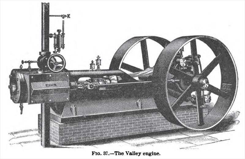
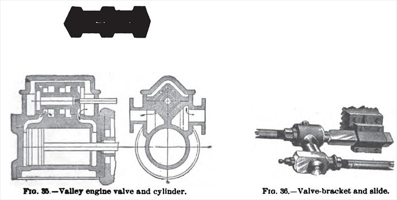
The Valley Engine.—Fig. 35 shows the balanced valve used by the Valley Iron Works, Williamsport, Pa., on their automatic high-speed engine. It consists of but one piece, and has no rings or sleeves. The shape is clearly shown in the illustration. It is set in the valve-seat, with the corner pointing to the center. Between the cover and cover-seat are placed strips of copper 1/100 in. in thickness, which are for the purpose of removal and taking up wear as the valve may require it. The objection to wear existing in the piston-valve is overcome by this construction. Live steam is admitted inside the cover around the valve, and exhaust let out at the ends. This construction admits of the engine being run under full boiler-pressure with the exhaust-cover removed, and an inspection of valve for leakage made under full steam-pressure. The construction of the valve-bracket and slide is shown in Fig. 36. The bracket is bolted to the bed and carries the slide, between the bracket and stuffing-box. On the valve-stem is a clamp-wrist, split in the back and pinched on the slide by a ½ in. bolt, as shown. In case of accident or of the valve striking the end of chest, this wrist will slip, preventing all damage. Fig. 37 is a perspective view of the engine. |
|
 1895 Valley Iron Works, The Valley Steam Engine
 1895 Valley Iron Works, The Valley Engine Valve & Cylinder
|
|