|
Title: |
1909 Article-Augustine Automatic Rotary Engine Co., Rotary Steam Engine |
|
Source: |
Practical Engineer, Dec 1909, pages 710-711 |
|
Insert Date: |
8/18/2012 9:36:09 PM |
THE AUGUSTINE ROTARY ENGINE WITH AUTOMATIC CUTOFF GOVERNOR AND BALANCED PISTONS
For developing a large amount of power in a small space, the Augustine Rotary Engine has proved itself well adapted and in many plants has shown itself to be a practical working machine requiring little attention and giving good satisfaction.
It has a number of novel features worked out through years of experiment by the inventor, Benj. F. Augustine, who is President of the Augustine Automatic Rotary Engine Co., of Buffalo, N. Y.
REGULATION
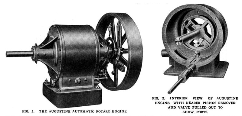
Illustrations herewith show the action of the engine and the design on which its success depends. In Fig. 1 is seen the assembled engine ready to run. It has a flywheel governor of special design which controls the speed accurately between no load and full load by changing the position of the eccentric.
This eccentric drives by means of an eccentric rod and rocker arm the oscillating valve, the driving mechanism being shown on the base of the engine in Fig. 1 and also at the bottom of the engine casing, Fig. 2. In Fig. 2, the ports through which the valve admits steam are in the bottom of the casing, one of them being seen where the revolving piston on the near side has been removed.
The ports in the casing are in line but the ports in the valve are staggered so that as the valve rocks back and forth steam is admitted first to one piston, then to the other. The pistons are mounted central to the outside casing, as shown in Fig. 2 and are held in this position by bearings in the heads, Fig. 3, these bearings being adjustable by means of set screws so as to keep the piston always bearing on the bottom of the eccentric abutment piece which forms the steam cylinder, this bearing being indicated in Fig. 2.
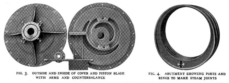
The abutment is shown by itself in Fig. 4, which also shows the ports for exhaust at the left and just the ends of the steam inlet ports at the right near the bottom.
PISTONS
The pistons revolve. They are 2 in number with flanges at the ends and between the 2 pistons, giving
steam-tight joints. These flanges fit down on either side of the abutments and are the full size of the bore of the outer casing.
In each piston is a counter-balanced blade seen in Fig. 1, the blade being at the lower right hand side of the piston and the counterbalance in a slotted arm of the piston at the upper left hand. This blade laps across the flanges of the piston so that the pressure of the steam seals them and makes a tight joint. These blades have, as shown in Fig. 3, a long arm on one side and a short arm on the other and on the ends of these arms, as shown in Fig. 2, are crossheads which run in grooves in the covers as indicated in Fig. 3, to keep the blades traveling central with the bore of the cylinder.
STEAM ACTION
As the piston blade crosses over the lower center of the engine, the valve rocks to open the port and admit
steam behind the blade; this forces the revolving piston around and the valve rocks to cut off steam at the point required by the load, as indicated by the governor action.
From this point of cutoff, expansion takes place and when the blade on one side reaches its uppermost position, the blade on the other side crosses the lower center and that piston begins to take steam. Thus one cylinder always has steam expanding while the other is taking steam at initial pressure. Steam exhausts without the action of a valve when the blade crosses the opening to the exhaust port shown in the abutment, Fig. 4.
Care has been taken to provide steam-tight joints at all points. On the inside edge of the abutment is a packing ring to bear against the flange on the piston. At the bottom of the abutment is a packing block to prevent any possible circulation of steam from the live steam to the exhaust steam side of the piston. The outer edges of the blades make, of course, a steam-tight joint with the abutment at all times. These joints are arranged to take up their own frictional wear and the careful design of the engine and the balancing of all parts is such as to reduce wear to a minimum.
The ends of the blades are housed in by the flanges of the pistons so that leakage cannot occur past these ends, and carrying the ends of the blades through to the crossheads which run in the heads or covers, insures accurate travel of these blades and freedom from vibration. The exhaust of the engine is so arranged that admission of steam and expansion take up about 320 deg. of the circle of revolution, and exhaust the remaining 40 degrees. The arrangement of the governor and valve is such that the engine can be reversed at any time and when running at any speed.
An idea of the compactness of the engine is had from the dimensions of 3 sizes. The 20-hp. has a height of 18 in. and a base 14 by 15 in., while the 45-hp. has a height of 27 in. and a base 20 by 24 in. A 100hp. engine recently installed in the planing mill of the Dodge-Bliss Co., at Tonawanda, N. Y., is 36 in. high, has a base 32 by 40 in., and a 4 -ft. flywheel.
Shop tests of the engine made on Mar. 20, 1909, at 95 to 102 lb. pressure, with the generator giving no volts and 104 to 112 amperes gave a water consumption of 622 lb. per" hour at 21 hp. and 631 lb. at 22 hp., or an average of 29 lb. an hour a horsepower. Five amperes was reckoned as the equivalent of an engine horsepower and all water was condensed and weighed. |
|
 1909 Augustine Automatic Rotary Engine Co., Rotary Steam Engine
 1909 Augustine Automatic Rotary Engine Co., Rotary Steam Engine Parts
|
|