|
Title: |
1910 Article-Augustine Automatic Rotary Engine Co., Rotary Steam Engine |
|
Source: |
Engineering News, V64, 15 Sep 1910, pgs 280-281 |
|
Insert Date: |
8/18/2012 10:47:58 PM |
The Augustine Rotary Engine.
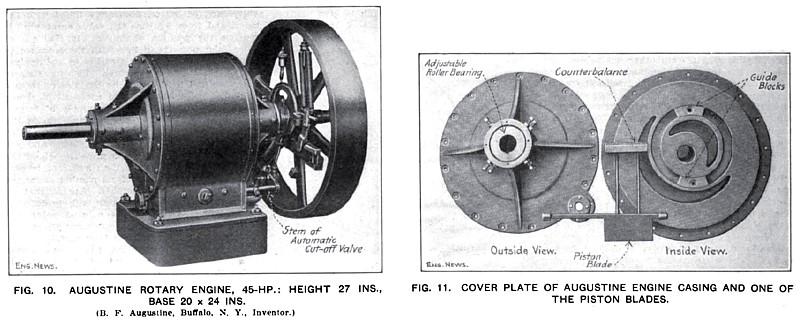
The Augustine rotary engine has a cylindrical rotor mounted on a shaft central to the rotor but eccentric to the cylinder (Class IV.). The working fluid acts upon a piston blade which moves radially In a slot In the rotor during each revolution. The blade is kept with its outer edge in contact with the cylinder walls by pins projecting from its two ends and carrying curved "cross-heads" which slide in grooves in the cylinder covers.
It is stated by the makers, the Augustine Automatic Rotary Engine Co., 73.8 Ellicott Square. Buffalo, N. Y., that half-a-dozen or more of these engines, of from 10 to 20 HP., have been put into regular and satisfactory operation driving blowers, etc., and one larger engine, of 100 HP., has been installed at a saw mill. A 45-HP. Engine of this type. Shown in Fig 10, is 27 ins. high and stands on a 20 x 24-in. base.
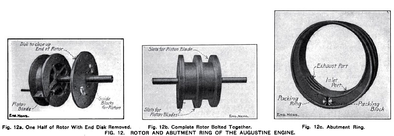
CONSTRUCTION.—The construction of the Augustine rotor is shown in Figs. 12a and 12b. In its assembled form, it consists of a hollow cylindrical cast-iron drum with projecting collars, or flanges, at each end and at mid-length. Each end of the hollow drum Is closed up by a cast-iron disk. The three flanges really serve as the side walls of two annular cylinders and also serve to support the piston blades when they are extended beyond the body of the rotor.
One of the piston blades is shown in Fig. 12a in position in the slots in the rotor flanges. Each of the two blades is balanced by a counterweight attached to two rods extending inward from the blade across the axis of the rotor. The form of the counterweight is shown in Fig. 11.
The two abutment rings, one of which is shown in Fig. 12c, are of the proper width to fit into the spaces between the flanges on the rotor. When assembled, the outer edges of the rings are even with those of the rotor flanges, and the under side of the body of the rotor Is in contact with the inner surface of the rings. The inner face of the ring forms the fourth wall of the annular cylinder space, whose other three walls are formed by the drum and flanges of the rotor itself. The opening through the ring is eccentric to its outer circumference so that the area of cross-section of the cylinder space gradually increases from zero, at the point of contact with the rotor at the bottom, to a maximum at the top. The piston blade is made to travel in a circle concentric with the eccentric opening by means of the curved guide blocks shown in Figs. 11 and 12a. which slide in circular slots in the cylinder cover.
Packing rings around the edges of the eccentric opening (Fig. 12c) are required to prevent leakage between the ring and the rotor flanges. As a further precaution, a "packing block" is placed between the ring and the flanges just below the point of contact of the ring and the rotor drum. This packing block is intended to prevent the passage from the pressure side over to the exhaust side of any possible leakage past the packing ring.
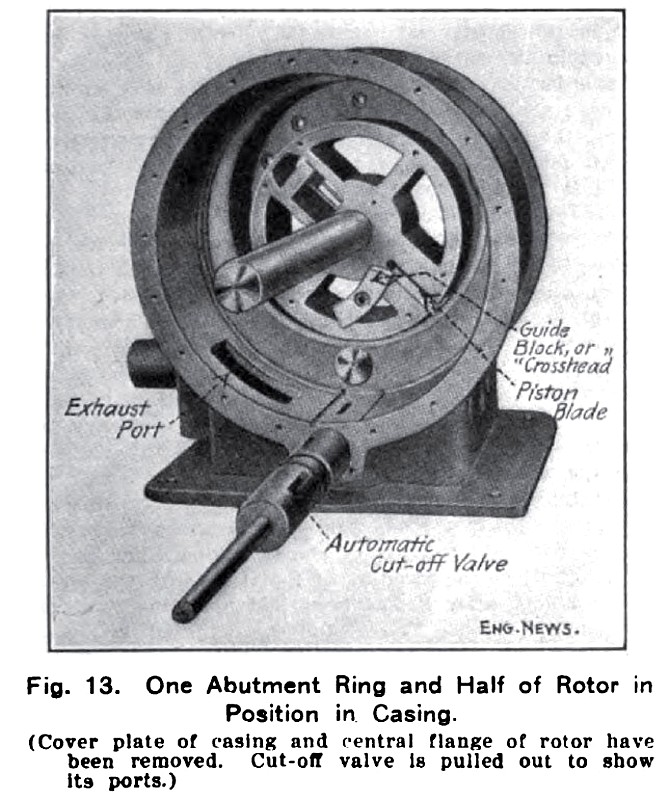
The abutment rings and rotor are enclosed in a plain cylindrical casing, whose two heads, or end covers, contain the roller bearings for the shaft. No stuffing boxes on the shaft are necessary in the Augustine engine. One-half of the rotor drum and one abutment ring are shown in position in the casing in Fig. 13. The shaft journals are made adjustable (see Fig. 11) so that the rotor drum can be brought down to the proper contact with the abutment rings.
The grated exhaust through the abutment ring (Fig. 12c) communicates with that shown in the casing in Fig. 13, which in turn is connected with the exhaust pipe. The cut-off valve is a hollow cylinder turning in a cylindrical chamber near the bottom of the casing. Steam is admitted through slots in the valve to corresponding slots through the walls of its chamber, whence it enters the cylinder through the inlet port in the abutment ring. In Fig. 13, the valve has been pulled out from its working position to show the ports. The cut-off valve is given an oscillating motion by an eccentric on the engine shaft and the point of cut-off is controlled by a fly-wheel governor.
OPERATION.—The rotor is show in Fig. 13 in about the position where admission occurs. The contact of the rotor drum with the abutment ring obstructs the escape in that direction of the entering steam, which therefore turns the rotor by pressing against the projecting piston blade. After cut-off, the rotor continues to revolve under the expansive pressure of the steam until the blade passes over the exhaust valve and the steam is permitted to escape. Revolution continues, under the action of the fly-wheel and of the second piston blade in the other half of the rotor, and the piston passes the point of contact with the abutment ring and is ready for the next stroke. The pistons in the two annular cylinders, separated by the middle flange on the rotor, are diametrically opposite so that both cannot be at the dead-point at the same time.
TESTS.—A 20-HP. Augustine engine was tested by the makers at the factory In March, 1909. No economy tests by a disinterested engineer are available. In the makers' test, the engine was direct-connected to an electric generator. The steam used was condensed and weighed and readings were taken of the steam gage in the supply main and of the voltmeter and ammeter in the generator circuit. In a one-hour run, 631 lbs. of steam were condensed. The steam gage reading averaged about 99 lbs. The voltmeter showed 110 volts and the ammeter reading averaged about 111. Assuming an efficiency of 85% for the generator, the brake horsepower developed was — 19.3 B. HP.; and the water rate was = 32.7 lbs. per B. Hp.-hr. If the generator efficiency is taken as 90%, the water rate becomes 34.6 lbs. |
|
 1910 Article-Augustine Automatic Rotary Engine Co., Rotary Steam Engine
 1910 Article-Augustine Automatic Rotary Engine Co., Rotary Steam Engine (Parts)
 1910 Augustine Automatic Rotary Engine Co., Rotary Steam Engine (Casing)
|
|