|
Title: |
1918 Article-Augustine Automatic Rotary Engine Co., Augustine Rotary Two-Cycle Gas Engine (Part 1) |
|
Source: |
Power Magazine, V47 No. 24, 11 Jun 1918, pg 828 |
|
Insert Date: |
8/19/2012 2:00:44 PM |
Augustine Rotary Two-Cycle Super-Induction Gas Engine
One of the most widely used engines for airplane work is the revolving air-cooled motor, of which there are several designs, operating on the four-stroke cycle. The distinguishing feature of this type of engine is that the crankshaft and cranks are stationary and the cylinders revolve about this shaft This produces the same relative motion of the piston to the cylinder as if the cylinder were stationary and the crank revolved, as in the case of an ordinary reciprocating engine. These engines are generally made with 5, 7, 9 or 14 cylinders and range from about 50 to 100 hp. each.
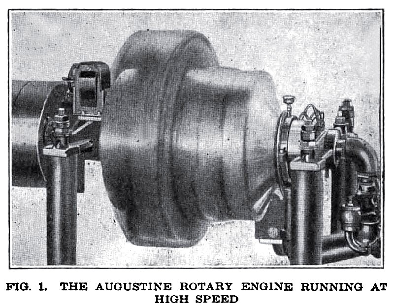
A new design of rotary gas motor is the Augustine rotary two-cycle super-induction air-cooled engine, Fig. 1, which has been developed by the Augustine Automatic Rotary Engine Co., 1862 Elmwood Ave., Buffalo, N. Y.
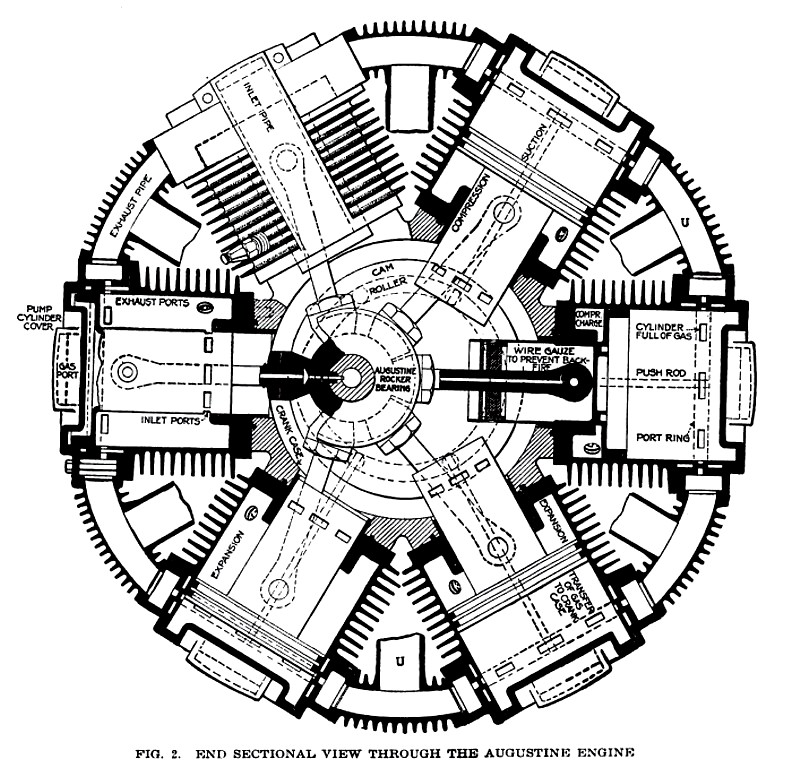
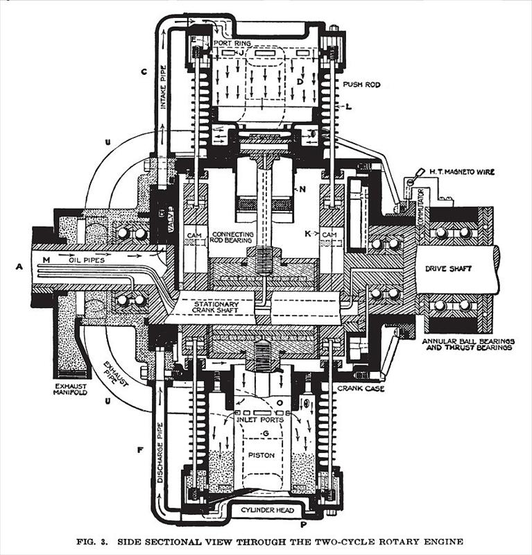
Figs. 2 and 3 illustrate the general design of this engine; the former is a sectional view through the motor in a plane at right angles to the axis of the driving shaft and centrally through the cylinders, also showing the relative positions of the pistons in the radial cylinders and the stationary shaft, bearings and connecting-rods. Fig. 3 is a sectional view in the plane of the axis of both the stationary and driving shafts, showing the assembled parts and how the lubricating oil is carried in copper tubes to the bearings and how the oil is kept cold by the incoming charge of gas.
The fuel gas is drawn from the carburetor through the hollow shaft A, Fig. 3, by the pumping action of the piston and is delivered to the crank casing, where it is put under slight compression, the degree of compression being controlled by the throttled condition of the carburetor. The passage of the fuel gas is from the hollow shaft A through the stationary controlling valve B and intake pipe C to the space D in the cylinder between the piston and the cylinder head, as shown by the arrows. As the sleeve valve E has closed the exhaust ports when the piston is at the compression position, the gas in the space D is forced back through the pipes C and F, past the valve B and into the crank casing of the engine when the piston begins its outward stroke, the valve B having moved to permit of its passage and so has cut off the supply of gas from the carburetor from the cylinder that has reached the compression stroke.
Fig. 4 is a sectional view of the stationary controlling disk valve showing the alternately intaking and discharging pipes that lead to the different cylinders. It also shows by the arrows the intaking of the charge from the carburetor and the discharging of the gas charge into the inner chamber by positive cutoffs above and below, the engine rotating in the direction of the curved arrow. As shown, the gas passes to the chamber D, Fig. 3, at the same time and is being forced into the crank casing from two opposite cylinders during the same period.
The fuel gas passes directly from the crank casing to the cylinders, entering through the intake ports G, Fig. 3, which are at the inner ends of the cylinders. A separate view of the piston, ports and cylinder is shown in Fig. 5, which also shows how the super-induction is effected, the sleeve E, Figs. 3 and 5, having closed the
exhaust ports and the full pressure of the inner chamber being admitted into the cylinder before cutoff and compression begin.
With the piston at the inner end of the cylinder, Fig. G, and the exhaust ports closed, the cylinder is filled with fuel gas drawn from the carburetor through the hollow shaft and intake pipe leading to the outer end of the cylinder. The greater piston area on the pump side is responsible for the super-charge that is brought in and then transferred to the inner chamber as the piston reaches the other end of the stroke. Compression is effected between the inner face of the piston and the inner end of the cylinder before exploding and expanding, and the spark plug H is located in the center of the charge. The screen on the intake ports / is to prevent backfiring.
After the explosion in any one of the six cylinders takes place, the burnt gases are expelled through the exhaust ports J, Fig. 3, at the outer end of the cylinders. These exhaust ports are controlled by a sleeve which is positively moved by the cams and push-rods K and L, the movement of the sleeve being so timed as to close the exhaust ports prior to the closing of the intake ports G. By this super-induction, brought about through the closing of the exhaust ports and the pumping capacity of the piston, which can deliver a large volume of gas to the cylinders, a very high volumetric efficiency is obtained, even at high altitudes in airplane service where low atmospheric pressures are encountered.
An idea of the action of the gases in each cylinder may be obtained from an examination of Figs. 7 and 8. The former shows the piston position just as the exhaust gases are released by the piston uncovering the ports and thereby relieving any pressure before the inlet ports are open. Fig. 8 is a similar view, showing the intake ports open and the cylinder fully scavenged of the burnt gases and the sleeve at the point of closing the exhaust ports. It also illustrates how the spark plugs H have a complete scavenge with the new, clean charge of dry gas, insuring easy ignition. As the exhaust ports are at the outer end of the cylinder and the inlet ports at the inner end of the piston cylinder, this prevents cycloning of the in-rushing gases and causes natural scavenging, owing to a "uniflow" of the gases.
In Fig. 9 is shown a partial view through the upper portion of a cylinder at one side, with the piston just closing the exhaust ports and the sleeve for the closing of the exhaust ports about to move and uncover them. At this position of the piston there is no pressure on the sleeve, therefore it is moved practically without friction. Fig. 10 is a similar view showing the exhaust ports uncovered by the sleeve and the piston just reaching the
space of the piston, forcing it outward and pulling on the fixed crank to turn the engine rather than thrusting against the crank. The expanding force of the gas against the piston operates in the same direction as the centrifugal force and is added thereto, and does not destroy the balance of one piston against the other. In this connection another advantage is accomplished in that the thrust of the expanding gases against the cylinder forces the cylinder against the crank casing, so that the only necessary connection between the cylinder and the crank casing is to overcome the centrifugal
ports, which it also uncovers and thereby effects the exhaust. After the compressed charge has been exploded and the piston has moved to its outer stroke, the sleeve valve E, Figs. 3, 9 and 10, uncovers the ports J and the incoming charge of fresh gas from the crank casing forces the burnt gases out through the ports J into the exhaust pipes V, Figs. 2 and 3. This cycle of events takes place in each cylinder in rotation.
In the operation of the rotary type of engine centrifugal force has to be contended with, and this becomes an enormous factor in a high-speed engine. The Augustine engine overcomes this difficulty by arranging the expansion and compression chambers for the fuel gases so that the expanding gases work against the inner
action on the cylinder. Records show that many accidents have occurred by the cylinder breaking loose through the tremendous pressure of the expanding gases combined with centrifugal effect, which tends to force the cylinder outward. In this engine, however, this is overcome because the pressure of the expanding gases against the inner end of the cylinder tends to hold it seated against the crank casing.
An essential feature in an airplane engine is extremely light weight. In this engine each cylinder is divided by the piston into a pumping chamber and an expansion and compression chamber for the fuel gases, as already mentioned. The gases are pumped by the same piston that is acted upon by the expanding gases, thus making the piston double-acting. By using the one cylinder both for pumping gases and for the expansion of the gases in turning the engine, the latter may be made very light, because the expansion of gases is against the inner end of the cylinder and the crank casing, and the outer end of the cylinder is only subjected to the suction and discharge of the gases. In other words, the force of the expanding gases is practically taken up by the piston head and the crank casing itself. As the sleeve that controls the gas ports is also timed to cover the exhaust ports when the outer end of the cylinder operates as a pumping chamber, this not only obviates the loss of fuel gases being pumped, but also prevents the burnt gases from being thrown back into the pumping chamber.
The cylindrical projection N, Fig. 3, extends inwardly from the piston head and from the housing from the piston-rod connection and also contains the intake port. This cylindrical projection is opened to the crank casing so that the cooled fuel gases pass up into them and the moist gases, particularly, are carried by centrifugal force into the cylindrical projection, which becomes in a way a vaporizer for gasifying the fuel. As the intake port are at the extreme inner end of the cylindrical portion carried by the piston, the moist gases are carried by centrifugal force past the intake ports and gasified, and only dried gas passes through the intake ports to the cylinder. Furthermore, the fuel gases come in contact with the inner central portion of the piston head, and at the same time the fuel gases in the pumping chamber come in contact with the outer face of the piston head. This tends to keep the piston head cool while the heat units tending to accumulate therein are utilized for gasifying the fuel.
The piston with its cylindrical projection has a two-point bearing, one at each end of the expansion chamber. As the piston travels, the connecting-rod assumes a position at an angle to the longitudinal center line of the cylinder, and this has caused considerable difficulty in previous engines, owing to the side thrust or twist of the piston wearing the cylinder wall. By this construction, however, where the piston has a two-point bearing, as at 0 and P, Fig. 3, this side thrust or lateral twist in the piston is taken care of with little or no wear of the piston on the cylinder wall. Furthermore, by this two-point bearing the extent of the contact surface between the piston and the cylinder wall is reduced to a minimum and the friction incident to the travel of the piston is thereby reduced.
The exhaust ports are large and are disposed about the end of the cylinder. The intake ports are disposed about the cylindrical portion carried by the piston and are in line with the exhaust ports. As a result, when the exhaust ports are open and the intake ports uncovered, the gases rush through the latter and force the burnt gases out of the former, thus scavenging the cylinder. As already stated, the central portion projecting from the piston prevents cycloning of the inrushing gases and intermixing with the burnt gases.
Each piston rod is connected to a pair of rings, and these rings are nested and engage two floating sleeves mounted on a fixed crank. By having a pair of rings, all side thrust on the piston rod is avoided. The end cups surround the ends of the connecting bars carrying the rings. A compression ring is slipped over the connecting bars and engages the groove therein. This compression ring also engages the inner surface of the cups and thereby forms in each cup a lubricating pocket. The oil for lubricating the crank is carried by a copper tube through the hollow fixed shaft as at M, Fig. 3, and passes out through oil grooves in and about the floating sleeve into the end cups and also out through the connecting-rod to the wristpin and to oil ducts leading to the cylinder walls. This arrangement gives lubrication for every desired part of the engine, and also insures that the fuel gases are free from the lubricating oil.
A side elevation through the center of the self-aligning bearing is given in Fig. 11, in which the two inner sleeves and the oil channels are shown, also the end cap bearings that inclose the outer section of the bearing. The two expansion rings on the inner ends of the caps are for retaining the oil film. Fig. 12 is an end view showing the various sections of the self-aligning bearing and the oil ducts leading up through the connecting-rods to the wrist-pin, through which the oil is equally distributed by centrifugal force through all parts while the engine is in operation. The ensemble of this self-aligning bearing insures alignment of the piston rods between the crank and the wrist-pin centers and at the same time constitutes the center along which all pistons and their rods revolve in a balanced centrifugal condition, with no reversal of direction of pull on the connecting-rods. Fig. 13 is a perspective view of two of the self-aligning bars with annular rings, which, when assembled, are mounted on inner creeping sleeves.
As the engine is of the two-stroke cycle type, the cylinders are fired in rotation one after the other. This gives a constant torque and permits of the use of a very simple ignition device; for example, in a six-cylinder engine a two-point magneto may be used, driven at a speed of three to one with a single wire leading to a brush-holder cooperating with spaced contacts connected to the respective spark plugs in each cylinder. The brush engages these contacts in rotation. The spark plugs are directly in front of the incoming gas, which assures perfect scavenging and allows the motor to be throttled to a very low speed and at the same time insures that the spark plug shall be in the region of the fresh fuel gas. A diagram showing the inlet and exhaust cycles of the motor and the section of the box cam that closes the exhaust ports in each revolution is shown in Fig. 14.
Following are given data of the more essential features of this engine: Number of cylinders, 6, having six double-acting pistons utilized both as power pistons and pumps; bore of working cylinder, equivalent in area to a 4 5/8-in. conventional piston; stroke, 4 in.; area of piston, 16.7 sq. in.; area of pump, 23.76 sq. in.; connecting-rod crank ratio, 4 to 1; bore of crank case, l0¼ in.; over-all diameter of motor, 26 in.; over-all length of motor, 24 in.: two-spark magneto, driven 3 to 1, giving six sparks per revolution; approximate weight of motor, 2 lb. per hp.; compression, from 90 to 100 lb. per sq. in.; positive system of force-feed lubrication.
The engine is started by turning the switch of the magneto and pressing the button of the self-starter. When the engine is stopped by turning off the switch all the cylinders are charged with fresh fuel from the inner chamber and are ready for the next operation. The engine can be started with a coil and battery if desired. It is made reversible by simply adding a sleeve to reverse the inlet and transfer ports. The engine is practically fool proof for the reason that there are no adjustments to be made. |
|
 1918 Augustine Automatic Rotary Engine Co., Augustine Rotary Two-Cycle Gas Engine
 1918 Augustine Rotary Two-Cycle Gas Engine (End Sectional View)
 1918, Augustine Rotary Two-Cycle Gas Engine (Side Sectional View)
|
|