|
Title: |
1895 Article-Mitts & Merrill, Key-Seater |
|
Source: |
Chicago Journal of Commerce, 31 Jan 1895, pg. 14 |
|
Insert Date: |
11/4/2012 11:04:53 AM |
AN IMPROVED KEY-SEATER
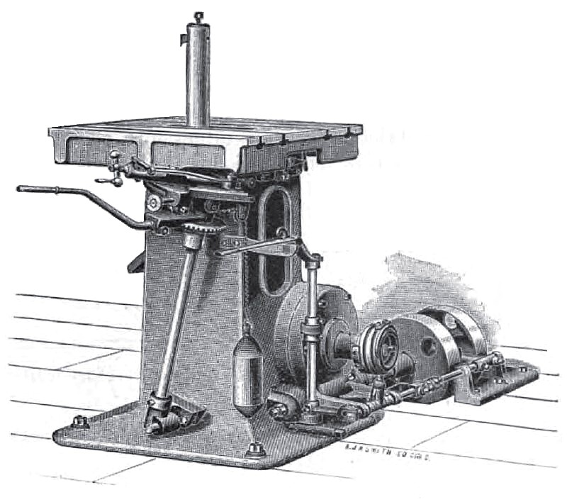
We present herewith an illustration of the Giant key-seater. The engravings show only the 14-inch stroke machine, they being built, however, in five sizes, ranging from 10-inch to 30-inch stroke, which are the normal strokes, the actual motion of the cutter being 1 inch or more greater.
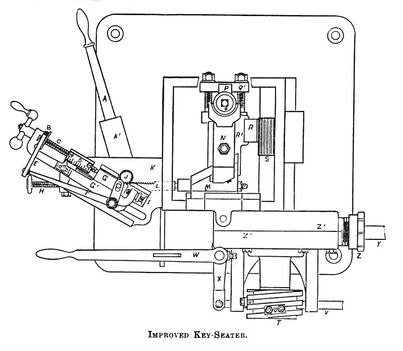
The column and worm gear casing is made of a single, heavy casting, thus avoiding extra joints and much increasing the rigidity of construction. The rack and pinion are cut from solid steel, the worm gear and screw (running in bronze bearings) are inclosed in the oil-tight gear casing, and the driving mechanism is a very powerful friction clutch, working silently and so quickly that the machine will operate with a stroke of less than 3/8-inch. To provide for straight or taper key-ways the table is arranged to tilt in either direction, the amount of taper being shown by a pointer on a graduated scale at the back of the machine. In operation the cutter bar is fed against the work, while the table remains stationary This arrangement entirely overcomes the difficulty which arises in obtaining the feed by moving the table, and, when in heavy work, the table is loaded with a weight of from 1,000 pounds up to several tons, as it frequently is, the advantage of moving the tool instead of the table becomes decidedly manifest. The cutter bars are made of steel and are round, the clumps for holding them being so arranged that the ordinary or special bars can be very quickly attached. A solid support for the cutter bars is placed close to the top of the table, which, with the large size of the bars, effectnally prevents deflection. The great strength and rigidity of all the parts with the powerful gearing, make the machine exceedingly effective for all ordinary work; occasionally, however, it becomes necessary to cut key-ways as long as the full stroke of the machine, where the hub may be elevated several inches above the table as by the rim of a pulley; in a case like this the cutter bar may spring back slightly when at its extreme upward stroke. To prevent all such springing, there is provided a simple attachment, which, inserted in the hub behind the cutter bar, affords a perfectly rigid support. . With the aid of this attachment it becomes possible to use long special cutter bars having two cutters, by means of which each end of a chambered hub, or both hubs, of a double-arm pulley can be cut at once, thus almost practically doubling the capacity of the machine on such work. The 14-inch stroke machine has in this way been used to cut key-ways 30 inches above the table. One noteworthy feature is the extreme case with which the cutter bar is moved and held against the pressure of the cut. It is well known to machinists who have had experience with different styles of key-seaters, that in some cases it is quite difficult to hold the tool into the cut, especially if it is dull. In a recent instance a machinist was seen with a strap thrown over his shoulders and attached to the operating lever, that he might at each stroke throw the whole strength of his body into the effort to hold the tool to its work. In the Giant key-seater, the guide bar, upon which the cross-head holding the tool bar slides, is so firmly locked in whatever position it maybe, yet is so easily moved by the operating lever, that the slightest touch is sufficient to control it. Referring to the outline engraving, which represents a plan of the key-seater, and shows some of the more important parts, the friction clutch pulleys are attached to the extended end of the shaft Y, and are operated by the rod V, which in turn is moved by the adjustable tappets U, attached to a helical grooved hub T. Z is the casing holding the worm gear and screw. S is a steel pinion which is as much wider than the rack R is the extent of the feed motion. P is the cutter, and O the cutter bar, which is clamped to the crosshead K, sliding on a guide bar which, extends the full length of the machine, and is rectangular in shape, very stiff and accurately fitted. In the larger sizes, this guide bar with the cross-head and cutter bar attached are quite heavy, and it would be difficult to move them easily were it not for the fact that the whole weight is hung in suspension, and practically all of the friction due to the weight is eliminated.
In operation, the two wedges M which are placed at each end of the guide bur serve to move it in both directions, and afford a solid support against the backward pressure of the tool.
The wedges M are moved by the operating lever A, which is attached to the shaft J having the pinions engaging in the racks L. The motion of the lever A is limited by the distance which the feed rack G can move between the ends of the feed screw C and the adjusting screw I. At each stroke the screw C is drawn out slightly to the amount of the feed. This can be done by hand or automatically through the lever F and pawl E acting on the ratchet B. The amount of feed can be varied to one or more notches on the ratchet by the adjusting screw I. The automatic feed greatly increases the capacity of the machine in many kinds of work. By means of the hand lever W the machine is instantly stopped, and can be started in either direction. In cutting key-ways the small pointer is set at the zero mark on the scale D, when the tool begins to cut, the depth being then indicated on the scale, and when it is finished the stop guage H can be screwed up against the end of the rack L, and after that any number of key-ways may be cut to exactly the same depth.
An attachment is furnished to bolt to the table for centering the work from the outside. To center the work by the hole there is a simple little device which slips onto the top of the cutter bar; as this can be put on and taken off after the work is on the table, it is much more convenient than the centeriug device formerly used, which required to be fastened to the table before the work could be placed. For holding work of large diameter there are furnished steel extension bars which fasten to the side of the table and are supported at the outer ends by jack screws.
For cutting racks or ratchets in steel or iron an extra rack-cutting attachment is made. The tools furnished for this purpose are of a proper shape and can be repeatedly ground without changing their form. For such work the machine is very effective.
Several parties using the midlines find them excellently adapted for cutting steel ratchet wheels and similar work, stating that it is far more satisfactory than doing it with milling cutters.
Special attachments can also be furnished for rapid key-seating in very light work. Recently key-ways which were 5/8 inch wide and 2 inches long were cut at the rate of 7 in 5 minutes, the pieces being chucked and removed without stopping the machine. Key-seats 6 inches long and ½ inch wide were cut in two steel pinions in 20 minutes which included the time of fastening and removing. A wheel weighing 1,200 pounds, and which was rather difficult to chuck, was put on and taken off of the machine in 55 minutes, the key-seat being 14 inches by 3/4-inch by 3/8-inch, the actual time of cutting being 9 minutes. These instances illustrate the great capacity of the machine, but it is more clearly shown where there are large numbers of duplicate pieces to be operated upon. It is very powerfully geared, the largest size cutting key-ways 3½ inches wide and 30 inches long, taking the full width at each cut.
The driving shaft is near the floor in the smaller machines, and in the large sizes it comes beneath the floor, being so arranged that the belts can come from any direction, the shaft and the rod which shifts the friction clutch may be of any length to put the belts entirely out of the way, thus the machine may stand in the middle of the floor and the belts be near the wall, offering no obstruction to the swing of cranes. The makers are Mitts & Merrill, Saginaw, Mich. |
|
 1895 Mitts & Merrill, Key-Seater
 1895 Mitts & Merrill, Key-Seater (Sectional View)
|
|