|
Title: |
1908 Article-The Huber Mfg. Co., Steam Traction Engine |
|
Source: |
The Traction Engine, Its Use and Abuse, 1908, pgs. 157-161 |
|
Insert Date: |
3/21/2014 10:44:21 PM |
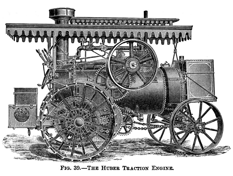
THE HUBER TRACTION ENGINE.
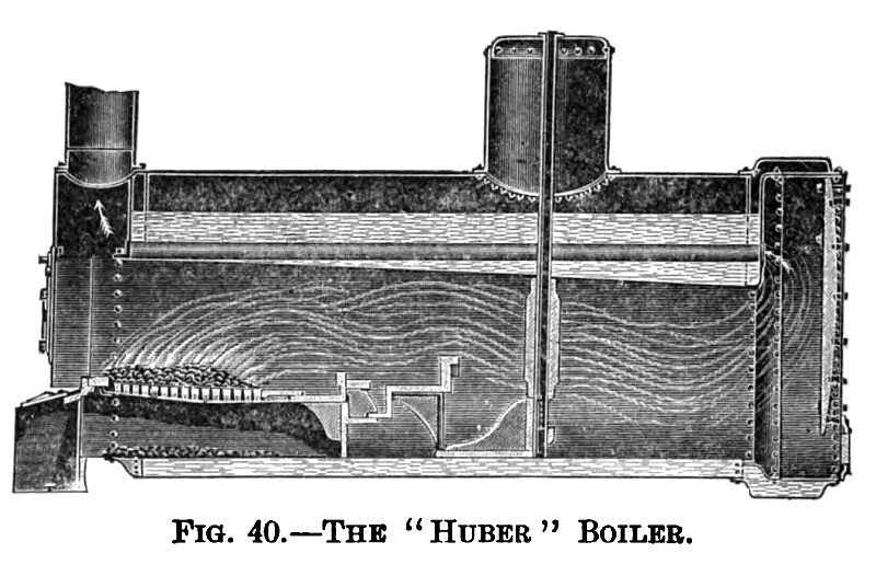
This engine belongs to the same class as the previous ones, which are using their boilers as frames for supporting the machinery. The wheel base is for this reason is very short. This company uses the return tubular type of boiler with the fire-box inside the large central tube and with the smokestack in the rear. It has a special super-heating device (see Fig. 40) consisting of a double tube, the outer one reaching from the steam dome down into the large fire-tube, and the inner one, constituting the steam delivery pipe, starting near the bottom of the outer one, carries the superheated steam through the dome to the engine. The combustion chamber in the front is provided with a hinged door on which the water-tank is mounted. By swinging back this door all the tubes are exposed and can be easily cleaned and inspected.
The smokestack is constructed of several layers of sheet iron with air spaces between, which construction leaves the outside surface of the stack relatively cool.
A variable exhaust is secured by having the exhaust nozzle divided by a central partition in two compartments and regulating the amount of steam blowing through one of them by a valve.
A cross-head pump, a siphon (see Fig. 10), and an injector take care of the water-supply.
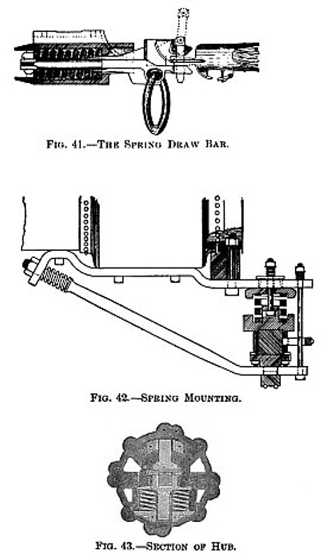
The engine is of the side-crank single-cylinder type, with cylinder, guide, and crankshaft bearings all in one casting. It has a belt-driven horizontal governor and the Huber reversing gear. The connection between the crank-shaft and the driving-wheel consists of a train of spur-gears. In this train of gears is also included a compensating gear which is constructed with spur-gears for pinions. This compensating gear is enclosed in a casing and covered by a steel plate, making it perfectly dust-free. Between the last gear and the driving wheels four spiral springs are introduced. Springs are also used between the drivers and the axle (see Fig. 43), between the front axle and the boiler (see Fig. 42), and between the draw-bar and the engine (see Fig. 41).
The driving wheels are of the built-up type with flat drop forged-steel spokes and rolled steel rims. The axle is square, does not revolve, and passes under the boiler from one wheel to the other. |
|
 1908 The Huber Mfg. Co., Steam Traction Engine
 1908 The Huber Mfg. Co., Steam Traction Engine (Boiler)
 1908 The Huber Mfg. Co., Steam Traction Engine (Details)
|
|