Image
|
Title: |
1894 Article-Hulse & Co., Ltd., Drilling Machine for Boilers |
|
Source: |
Scientific American, V 71 #2, 29 Jul 1894, pg. 23 |
|
Insert Date: |
5/20/2014 5:49:00 PM |
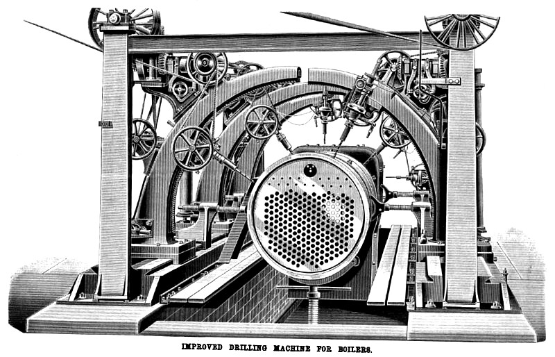
IMPROVED DRILLING MACHINE FOE BOILERS.
To insure satisfactory results in the manufacture of steam-boilers for high working pressure it is generally stipulated that all holes in the plates shall be drilled, and not punched or reamered, and that the bent or curved portions of the boiler shall be drilled after being bent. The holes in the flat portions of the boiler are readily dealt with in vertical or horizontal drilling machines with single or multiple spindles, but the curved portions, such as the barrel and flanged corners of the fire box shell of a locomotive boiler, require special treatment, and the machine which is illustrated below has therefore been devised.
It will be seen that the boiler shell, after being completely built and tacked together with a few service bolts, is placed horizontally in the machine, and there held by suitable screw apparatus. The upper half is then operated upon by the several drills; and afterward the boiler is moved half way round, and the holes in the remaining portion drilled, thus completing the work with only one shift of the job. It is obvious that this method of drilling insures absolute coincidence of the rivet holes, a matter the importance of which needs no comment: and, although several machines have been devised for the simultaneous action of several drills upon one and the same job, we do not know of any one which—to the same extent as the machine illustrated—combines this qualification with such completely independent and universal action of the drill spindles.
The Engineer, London, to which we are indebted for our illustration and the particulars here given, says the machine has been designed and patented by Mr. C. M. Davies, M.I.M.E., and recently constructed by Messrs. Hulse & Co., Ordsal Works, Manchester, for Messrs. Dubs & Co., of the Glasgow Locomotive Works —where it is now in full operation. It has two horizontal slide beds, placed respectively on opposite sides of a pit, with vertical standards carrying the self-contained counter-shafting attached to the ends of each.
In the bed« are racks by means of which the several drilling headstocks may be traversed by hand and power in either direction for quickly adjusting the drills in lines parallel with the axis of the boiler. Fitted to the beds are sliding saddles with circular tee slides on their upper surfaces, affording radial adjustment to the drill spindles in horizontal lines. Segmental arms surmount the saddles, and are fitted with spindle slides adjustable radially thereon by curved racks. The spindles are thus made to point always to the axis of boiler when drilling the horizontal and circular seams of the barrel, but there is yet another adjustment provided for each spindle, namely, a vertical radial adjustment, enabling it to drill holes in various planes parallel to each other, as in rectangular fire boxes, or at angles with each other, as in curved fire boxes. Rotary motion is transmitted from the counter-shaft to the drill spindles by means of endless leather bands and bevel gearing, tension apparatus being fitted to each drilling headstock for always keeping the band tight, and friction clutches for applying and suspending the rotation of each spindle independently. An independent self-acting feed motion by screw and differential gear is provided for each spindle, and a quick hand traverse in and out. The machine illustrated has six drill spindles, but this number may be varied according to requirements. |
|
 1894 Hulse & Co., Ltd., Drilling Machine for Boilers
|
|
|
|