|
Title: |
1849 Article-Brown & White, Compound Slide Lathe for Turning |
|
Source: |
Scientific American, V 4 #16, 06 Jan 1848, pg. 121 |
|
Insert Date: |
12/29/2015 1:41:59 PM |
This is a Turning Lathe invented by J. D. White,of Hartford, Connecticut,who has taken measures to secure a patent for his ingenious improvement.
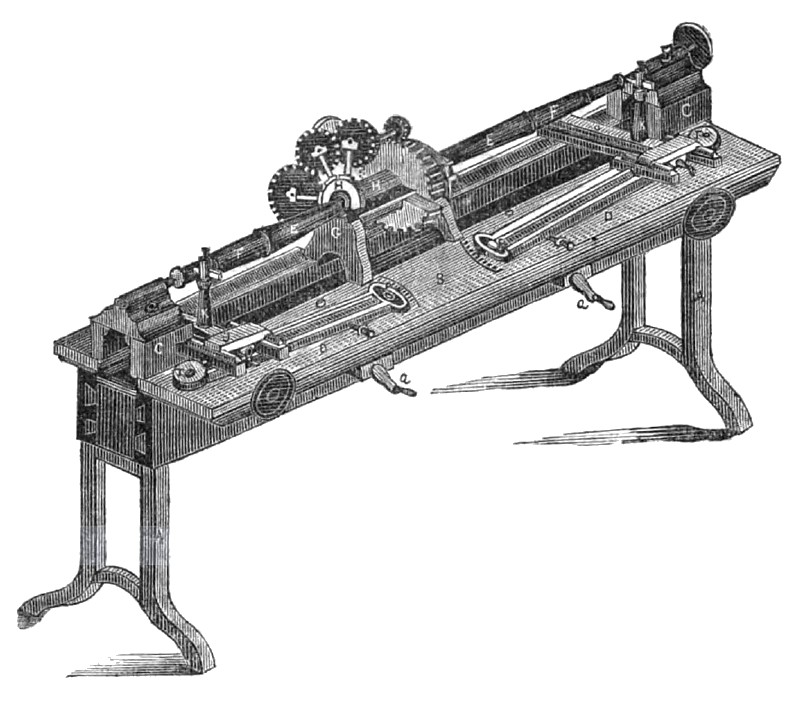
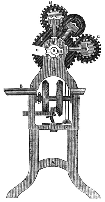
Fig. 1, is a perspective view of the lathe and fig. 2 is a transverse section taken at the left end of the chuck. This invention relates to the turning of axles with two slides and cutters one at each end, but it principally relates to having moveable ways that can move the tool stock to any angle with the revolving axis so as to turn shafts of any taper. By moving the slide parallel with the rotating axis, the cutter will make journals or shafts of equal diameter throughout with equal facility. A, is the frame of the lathe, and B is the table of the common form. C C, are two tail blocks and G two central headstocks to receive the chuck H. E, is the axle to be turned. This axle is placed sideways in the chuck through an opening in the chuck spur wheel I, and the chuck itself, so as to centre the axle in an easy manner. D D, are two moveable ways. J J, are slides of the tool stocks K. The slides move on the rail of the moveable way and are guided by it to cut at any angle. This is done by securing the bottom plate of the moveable way to the end of the table by a vertical axis or pivot T, and securing the way, D, at the other end on the table by a set-screw —The latter end of the way has a small slot P, in it, so as to let the moveable way be moved out and in at that end to and from the axle to be turned This is done by a worm screw of which a a, are the handles. This screw passes through a vertical bar attached to the bottom of D D, passing through the table and as this bar has an eye with an interior thread in it, it will be observed that the way at one end will be moved by the slot P, while the other end of the way will only move on its vertical axis. By setting the way in this manner, the tools will cut at the desired angle, which may be indicated by a pointer on the sliding end of the way, and an index on the table.
In turning axles, this compound lathe answers the purpose of two lathes, for the one, cutter can turn the journal at one end while the tool is cutting the taper F, at the other end. The moveable way is a very useful and simple improvement and can be applied to any lathe.
In fig. 2, the opening 0, of the spur wheel and chuck is better seen. The chuck is revolved by a spur wheel I, which is fixed around it like a ring. M N, are two spur wheels driven by a smaller spur wheel on the shaft of the pulleys which is between M and N. The use of the two spur wheels to drive I, is for one to be in gear with it while H, is a coupler which is screwed on to the axle and by a pin projecting into the slot of the chuck, when the chuck will be revolved the axle will thus be revolved with it.
The gearing in fig. 2 seen below G is the double feed tearing to move the slides of the tool stocks in the usual way. This gearing is driven by a band from a pulley above. We have not lettered these for description, as it is a double slide gearing operating in combination the two slides of the tool stocks. This compound lathe has received much commendation especially the simple plan of operating the slides.
US Patent: 7,390.
http://datamp.org/patents/displayPatent.php?number=7390&typeCode=0 |
|
 1849 Brown & White, Compound Slide Lathe for Turning
 1849 Brown & White, Compound Slide Lathe for Turning (End View)
|
|