|
Title: |
1852 Article-Samuel Worssam & Co., Timber Sawing Frame |
|
Source: |
Scientific American, V 8 #7, 30 Oct 1852, pg. 49 |
|
Insert Date: |
11/7/2014 10:41:28 PM |
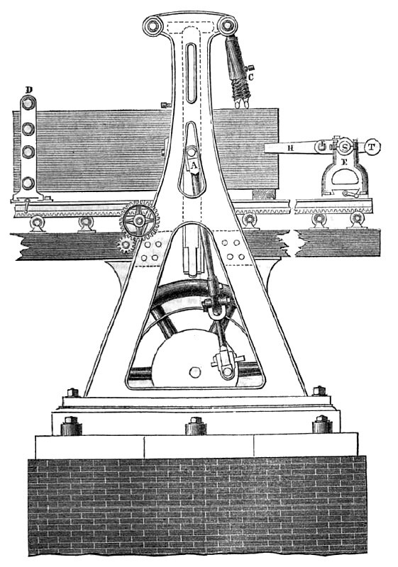
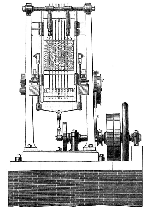
The annexed engravings are a tide elevation (figure 1) and a transverse elevation (figure 2) of a timber sawing frame, constructed by Messrs. Worssam & Co., engineers, of London. We have selected this from the London Artisan, knowing that a great number of our readers are interested in sawing machinery, consequently they like to see and know how such machinery is arranged, constructed, and used in other countries beside our own.
In arranging the building of a heavy timber frame, the foundations are ordinarily a heavy item, from the great depth required by the length of the connecting rod; and if this is curtailed, the evil is entailed ol sufficient friction on the guides. In the case before us, the makers have sought to reduce the height of the machine, by making the connecting rod forked, so as to embrace the frame, to both sides of which it is attached at the points, A A. To admit the vibration of the connecting rod, the guides are suitably overhung.
In the guides themselves, attention has been directed to diminish the friction, which, in surfaces, moving at such a high velocity, consume a large proportion of the applied power. With this object, the back and front guides are not both V-shaped, as usual, but whilst the working side is made so, the other side is made flat, and has a brass plate pressed in contact with it by means of a steel spring, set up by adjusting screws to the exact pitch to keep the frame from chattering.
The lower saw buckles are of S-shape, and hook on to a projecting feather on the frame. They are set up sideways by a longitudinal screw, passing through all the distance pieces, but not through the saw buckles, so that any saw can be taken out in a few minutes.
The timber is prevented from rising, when the saws are entering, by the two legs, C C, which are screwed, (with double threads) into sockets hanging from one of the strong distance pieces, between the sides of the framing. When adjusted to the proper length, they can be fixed in position by set screws.
Provision is made for setting the log transversely. The frames, D and E, on which the ends ot the log are carried, are fitted up in the slide-rest style, and can be shifted by the screws across the rack-bed. They are made to suit the varying widths of timber, by one of the arms, H, being made a fixture on the shaft, S, whilst the other slides on the shaft, and is moved by a screw, I, to give the requisite grip of the wood. A balance-weight, T, facilitates the adjustment. The other end, D, is provided with set screws for the same purpose.
The feeding-motion is as usual; the eccentric rod, N, taking on to a ratchet-wheel, for the feed, and a strap between the riggers, O, and P, giving the quick return motion for the rack.
The London Artisan asks its readers to give some particulars about the indicated power required for saw frames, in America five horse-power is allotted for driving a large rip saw, and a large circular saw. Gang saws are now common in American sawmills; but the common mode of working the reciprocating saw, is nearly the same as that represented above. An engine of three horsepower will drive one of these saws, but it is best to leave a good margin of power as a surplus; it is more profitable to do this than to work an engine or water wheel up to its full indicated power. |
|
 1852 Article-Samuel Worssam & Co., Timber Sawing Frame (Side View)
 1852 Article-Samuel Worssam & Co., Timber Sawing Frame (Front View)
|
|